
Microelectronics world news
It's Wednesday, so here's my small apartment workbench. Moving to a new place soon and I hope I get more space.
 | submitted by /u/OftenDisappointed [link] [comments] |
A faulty memory IC caused Voyager 1 to send incoherent messages. After 5 months, scientists figured out how to work around it and restore communications.
 | submitted by /u/1Davide [link] [comments] |
Three Software Companies Show Off Support Tools at Embedded World
Power Tips #128: Designing a high voltage DC-link capacitor active precharge circuit

Introduction
Electric vehicles (EVs) typically feature a large DC link capacitor (CDC LINK) to minimize voltage ripple at the input of the traction inverter. When powering up an EV, the purpose of precharging is to safely charge up CDC LINK before operating the vehicle. Charging CDC LINK up to the battery stack voltage (VBATT) prevents arcing on the contactor terminals, which can lead to catastrophic failures over time.
The conventional precharge method involves implementing a power resistor in series with the CDC LINK to create a resistor-capacitor (RC) network. However, as the total CDC LINK capacitance and VBATT increase, the required power dissipation grows exponentially. In this article, we’ll present a straightforward approach to designing an efficient, active pre-charge circuit using a spreadsheet calculator.
Understanding active precharge
While passive precharge employs a power resistor to create an RC circuit that charges the capacitor asymptotically, active precharge can employ a switching converter with a buck topology that uses hysteretic inductor current control to deliver a constant charge current to the capacitor (Figure 1).

Figure 1 The active precharge circuit where a buck converter uses a hysteretic inductor current control to deliver a constant charge current to the capacitor to enable the linear charge of the capacitor voltage (VCAP) up to the same voltage potential as the battery (VBATT). Source: Texas Instruments
This constant current enables linear charging of the capacitor voltage (VCAP) up to the same voltage potential as that of the battery. Figure 2 and Equation 1 characterize this linear behavior.
![]()

Figure 2 Active precharge linear behavior using a buck topology with hysteretic inductor current control. Source: Texas Instruments
The first step is to determine the required charge current (ICHARGE). ICHARGE is the quotient of the total DC link charge (QDC LINK) and the required precharge time (tCHARGE) shown in Equation 2.

QDC LINK is the product of CDC LINK and VBATT, as shown in Equation 3.
![]()
Calculator overview
This active hysteretic buck circuit has a floating ground potential riding on the switch node, so powering the control system requires an isolated bias supply. The calculator tool will ensure that the power consumption of this control circuitry stays within the sourcing capability of the isolated bias supply, or else the voltage will collapse.
The High-Voltage Solid-State Relay Active Precharge Reference Design from Texas Instruments (TI) introduces an active solution that enhances energy transfer efficiency and reduces practical charge time. TI’s TPSI3052-Q1 is a fully integrated isolated bias supply used in the active precharge reference design, which can source and supply up to 83 mW of power to the isolated secondary. Gate drive current, device quiescent currents, and resistor dividers are the primary contributors to power consumption. Equation 4 characterizes the gate drive power (PGATE DRIVE) as the product of the gate drive current (IGATE DRIVE) and gate drive voltage (VS GATE DRIVER) which is 15 V, in the case of the reference design.
![]()
Equation 5 characterizes gate drive current as the product of the metal-oxide semiconductor field-effect transistor (MOSFET) total gate charge (QG) and switching frequency (FSW).
![]()
Equation 6 expresses how FSW varies according to VCAP throughout the charging period, creating the upside-down parabola in the FSW versus VCAP curve in Figure 3. As shown in the Figure, the gate drive current peaks at the maximum switching frequency (FSW_MAX), which occurs when VCAP reaches half of VBATT. Equation 7 expresses the relationship between FSW_MAX, VBATT, inductance (L) and peak-to-peak inductor current (dI):

![]()

Figure 3 Calculator curve showing FSW versus VCAP and FSW LIMIT. Source: Texas Instruments
Using the calculator tool
The calculator prompts you to input various design parameters. The yellow cells are the required inputs while gray cells signify optional inputs. The default values in the gray cells reflect the parameters of the reference design. A user can change the gray cell values as needed. The white cells show the calculated values as outputs. A red triangle in the upper-right corner of a cell indicates an error; users will be able to see a pop-up text on how to fix them. The objective is to achieve a successful configuration with no red cells. This can be an iterative process where users can hover their mouse over each of the unit cells to read explanatory information.
Precharge system requirements
The first section of the calculator, shown in Figure 4, computes the required charge current
(ICHARGE REQUIRED) based on the VBATT, tCHARGE, and CDC LINK system parameters.

Figure 4 The required charge current (ICHARGE REQUIRED) based on the VBATT, tCHARGE, and CDC LINK system parameters. Source: Texas Instruments
Inductance and charge current programming
The section of the calculator shown in Figure 5 calculates the actual average charging current (ICHARGE) and FSW_MAX. The average inductor current essentially equates to ICHARGE where ICHARGE must be equal to or greater than ICHARGE REQUIRED, this was calculated in the previous section to meet the desired tCHARGE.
Be mindful of the relationship between L, dI, and FSW_MAX as expressed in Equation 7. L and dI are each inversely proportional to FSW, so it is important to select values that do not exceed the maximum switching frequency limit (FSW LIMIT). Your inductor selection should accommodate adequate root-mean-square current (IRMS > ICHARGE), saturation current (ISAT > IL PEAK), and voltage ratings, with enough headroom as a buffer for each.

Figure 5 Inductance and charge current programming parameters. Source: Texas Instruments
Current sensing and comparator setpoints
The section of the calculator shown in Figure 6 calculates the bottom resistance (RB), top resistance (RT), and hysteresis resistance (RH) around the hysteresis circuit needed to meet the peak (IL PEAK) and valley (IL VALLEY) inductor current thresholds specified in the previous section. Input the current sense resistance (RSENSE) and RB. These are flexible and can be changed as needed. Make sure that the comparator supply voltage (VS COMPARATOR) is correct.

Figure 6 Section that calculates the bottom resistance (RB), top resistance (RT), and hysteresis resistance (RH) around the hysteresis circuit needed to meet the peak (IL PEAK) and valley (IL VALLEY) inductor current thresholds. Source: Texas Instruments
Bias supply and switching frequency limitations
The section of the calculator shown in Figure 7 calculates the power available for switching the MOSFET (PREMAINING FOR FET DRIVE), by first calculating the total power draw (PTOTAL) associated with the hysteresis circuit resistors (PCOMP. RESISTORS), the gate driver integrated circuit (IC) (PGATE DRIVER IC), and the comparator IC (PCOMPARATOR IC), and subtracting it from the maximum available power of the TPSI3052-Q1 (PMAX_ISOLATED BIAS SUPPLY). Input the MOSFET total gate charge (QG TOTAL), device quiescent currents (IS GATE DRIVER IC and ISUPPLY COMP IC), and gate driver IC supply voltage (VS GATE DRIVER IC). The tool uses these inputs to calculate FSW LIMIT displayed as a red line in Figure 3.

Figure 7 Isolated bias supply and switching frequency limitations parameters. Source: Texas Instruments
The calculator tool makes certain assumptions and do not account for factors such as comparator delays and power losses in both the MOSFET and the freewheeling diode. The tool assumes the use of rail-to-rail input and output comparators. Make sure to select a MOSFET with an appropriate voltage rating, RDSON, and parasitic capacitance parameters. Ensure the power loss in both the MOSFET and freewheeling diode are within acceptable limits. Finally, select a comparator with low offset and low hysteresis voltages with respect to the current sense peak and valley-level voltages. Simulating the circuit with the final calculator values ensures the intended operation.
Achieved the desired charge profile
Adopting an active hysteretic buck circuit significantly improves efficiency and reduces the size of the charging circuitry in high voltage DC-link capacitors found in EVs. This helps potentially lower the size, cost, and thermals of a precharge solution.
This article presents the design process to calculate the appropriate component values that help achieve the desired charge profile.
By embracing these techniques and tools, engineers can effectively improve the precharge functionality in EVs, leading to improved power management systems to meet the increasing demands of the automotive industry.
 Tilden Chen works as an Applications Engineer for the Texas Instruments Solid State Relays team, where he provides product support and generates technical collateral to help win business opportunities. Tilden joined TI in 2021 after graduating from Iowa State University with a B.S. in Electrical Engineering. Outside of work, Tilden enjoys participating in Brazilian jiu-jitsu and shuffle dancing.

Hrag Kasparian, who joined Texas Instruments over 10 years ago, currently serves as a power applications engineer, designing custom dc-dc switch-mode power supplies. Previously, he worked on development of battery packs, chargers, and electric vehicle (EV) battery management systems at a startup company in Silicon Valley. Hrag graduated from San Jose State University with a bachelor of science in electrical engineering.
Related Content
- Power Tips #127: Using advanced control methods to increase the power density of GaN-based PFC
- Power Tips #126: Hot plugging DC/DC converters safely
- Power Tips #125: How an opto-emulator improves reliability and transient response for isolated DC/DC converters
- Teardown: The nuances of variable-frequency drives
The post Power Tips #128: Designing a high voltage DC-link capacitor active precharge circuit appeared first on EDN.
UK’s CSA Catapult and Sarawak’s SMD sign MoU
I've had batteries leaking before, but this is first I've found like this.
 | submitted by /u/tsraq [link] [comments] |
NORD DRIVESYSTEMS at ACHEMA 2024
NORD drive solutions for the process industry
From 10 to 14 June 2024, NORD will be presenting a wide range of products at ACHEMA in Frankfurt am Main. The focus is on ATEX-compliant drive concepts for the process industry and the robust heavy-duty MAXXDRIVE® industrial gear unit, in particular for agitator and mixer applications. Further focal points at the trade fair will be the new decentralised NORDAC ON/ON+ frequency inverters, the revolutionary DuoDrive geared motors and IE5+ synchronous motors as well as the NORDCON APP with NORDAC ACCES BT. Interested trade visitors can find out more about NORD’s wide range of solutions at the trade fair grounds in Frankfurt am Main in Hall 8.0, Stand B52.
Whether in the chemical, pharmaceutical or food industries: Companies that extract, transport or process raw materials require industry-specific, innovative drive solutions. As a system supplier, NORD offers matched drive systems consisting of gear unit, motor and drive electronics that are tailored to the respective requirements of the customer application.
ATEX drives for explosion-protected areas Flammable gases and dust in processing industries create serious safety risks. NORD has decades of experience with gas and dust explosion protection and offers particularly robust electric motors with powers from 0.12 to 200 kW especially for this field of use. The explosion-protected electric motors can be operated in category 2D or 3D dust atmospheres (zones 21 and 22) as well as in category 2G or 3G gas atmospheres (zones 1 and 2) and are approved according to ATEX and HazLoc. The dust-protected motors feature the ignition protection category “Protection by enclosure” (tD). Depending on the requirements, the motors in the gas explosion protection version are available in the following ignition protection classes: increased safety
(e), pressure-resistant encapsulation (d/de) and non-sparking design.
Industrial gear units for high torque applications NORD’s MAXXDRIVE® industrial gear units power heavy-duty applications such as agitators, mixers and grinders in food or cosmetic production. The parallel and right-angle gear units cover a speed ratio range from 5.54:1 to 400:1 – and with a first-stage gear unit, even up to 30,000:1. They feature:
• High output torques from 15 to 282 kNm for reliable operation even under extreme conditions
• Torsionally rigid, one-piece UNICASE housing for a longer bearing life and efficient power transmission
• Large low-friction roller bearings for extremely high radial and axial load capacities and a long service life
• High-precision axis alignment for guaranteed quiet running
For mixer and agitator applications, the industrial gear units can also be equipped with a SAFOMI-IEC
adapter:
• The adapter is available for parallel gear units and in sizes 7 to 11, i.e. for maximum output torques from 25
to 75 kNm.
• The adapter is compact and simple in design and has an integrated oil expansion volume; oil tanks and hoses as well as the radial shaft seal that is subject to leakage and wear between gear unit and IEC cylinder are therefore not required.
The NORDAC ON frequency inverters are part of the NORD modular system and can be optimally combined with the manufacturer’s motors.
• NORDAC ON was designed for applications with asynchronous motors,
• NORDAC ON+ was designed for the combination with highly efficient IE5+ synchronous motors.
The inverters are designed for power ranges from 0.37 to 3 kW.
The IE5+ motor generation from NORD DRIVESYSTEMS guarantees the highest level of efficiency and operational reliability, thanks to IE5+ technology. The motors are available as a TENV smooth-surface motor, as a TEFC motor with cooling fins and as an integrated DuoDrive motor. The latter combines a highefficiency IE5+ motor and a single-stage helical gear unit in one housing. The IE5+ synchronous motors with motor efficiencies of up to 95% are available in the TEFC version with a power of up to 4.0 kW, in the TENV
version with up to 2.2 kW and in the DuoDrive version with up to 3.0 kW.
With the NORDCON APP for mobile maintenance and commissioning of NORD frequency inverters, NORD enables the diagnosis, analysis, parametrisation and monitoring of the drive systems via a mobile terminal device for service use. The NORDAC ACCESS BT is a Bluetooth stick that is used directly with the frequency inverter – this ensures convenient mobile access to the drive data while at the same time access control.
NORD will present its comprehensive range of solutions at ACHEMA in Hall 8.0, Stand B52.
The post NORD DRIVESYSTEMS at ACHEMA 2024 appeared first on ELE Times.
AquiSense’s UV-C LED technology integrated into International Space Station’s water dispenser
Rohde & Schwarz expands footprint in India by opening new state-of-the-art facility in Bengaluru
On April 22, Rohde & Schwarz inaugurated a new facility center in Bengaluru’s Manyata Tech Park, housing R&D, system integration as well as calibration and repair services. The opening marks a strategic milestone for the technology company: it not only increases its presence in the third-largest city in India, but also strengthens its commitment to the Make in India initiative of the government by fostering innovation across the automotive, telecom, semiconductor, electronics, aerospace and defense sectors.
Rohde & Schwarz India, the Indian subsidiary of the German-based, global technology company Rohde & Schwarz, celebrated the grand opening of its new future-oriented facility located in the heart of Bengaluru’s prestigious Manyata Tech Park.
 Andreas Pauly, President and Chief Technology Officer (CTO) of Rohde & Schwarz
While inaugurating the new offices, Andreas Pauly, President and Chief Technology Officer (CTO) of Rohde & Schwarz, said: “We are proud to expand our presence in Bengaluru. For Rohde & Schwarz, India is not merely a growth market but a vital component of our global strategy. The new facility marks a significant milestone in our journey toward strengthening our position as a trusted partner in India’s evolving technological landscape. Moreover, it reflects our contribution to the Make in India initiative through a large team of highly skilled engineers.”
For more than 90 years, Rohde & Schwarz has had a tradition of innovation, helping to develop current and future cutting-edge technologies. By expanding R&D activities in India, Rohde & Schwarz is able to enhance technological excellence for the highly dynamic Indian market. The R&D team in Bengaluru is involved in developing next-generation solutions for the company’s Test and Measurement Division.
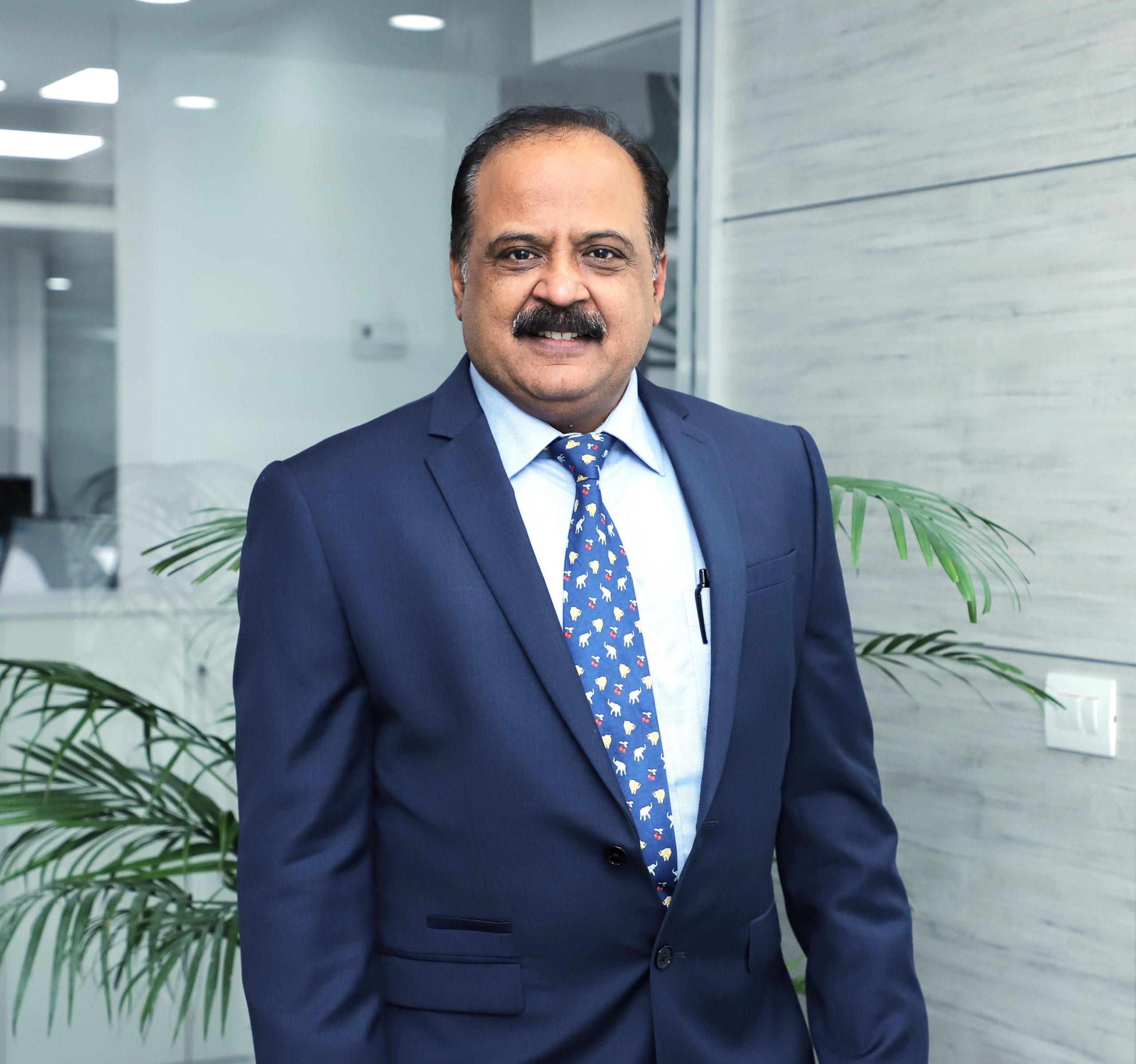 Yatish Mohan, Managing Director Rohde & Schwarz India
Yatish Mohan, Managing Director, Rohde & Schwarz India, added: “For the past 25 years, we have fostered technological advancement in India through strategic partnerships with government agencies, training institutes and technology firms. Our presence spans multiple locations throughout the country, encompassing tier-II cities directly and via our extensive channel partner network. We are excited about the opportunities that our new facility brings, allowing us to enhance our services to the Indian technology industry and facilitate innovation in the electronics, semiconductor, automotive and telecommunications sectors.”
The new facility houses an ISO 9001 and ISO17025 (NABL) accredited calibration and repair service center, offering precision services to meet the rigorous quality standards of the industry. This addition reinforces the commitment of Rohde & Schwarz to delivering high-quality products and services to its customers across India and beyond. Furthermore, the facility will also encompass sales, applications, systems integration and a dedicated demo display area showcasing various test and measurement equipment and test solutions. This strategic move underscores the company’s intention to enhance customer experience and accessibility, providing clients with hands-on experiences and seamless access to cutting-edge technology solutions.
The post Rohde & Schwarz expands footprint in India by opening new state-of-the-art facility in Bengaluru appeared first on ELE Times.
Intel First to Install High NA EUV Lithography Scanner
PCIM Giveaway: Enter to win a 14” MacBook Pro
Learning the art of making PCB's, this is my progress over a year.
 | submitted by /u/External_Asparagus10 [link] [comments] |
Toyoda Gosei develops high-output UV-C LED
SiTime Trumpets New Integrated Clock Chip as a First for AI Data Centers
Lumentum awarded Platinum EcoVadis Medal for second consecutive year
Keysight introduces next-gen RF circuit simulator
ROHM’s SiCrystal and ST expand silicon carbide wafer supply agreement
Palladium emulation: Nvidia’s Jensen Huang is a fan

Nvidia CEO Jensen Huang calls Palladium the only appliance more important to him than the refrigerator. At Cadence Design Systems annual event in Santa Clara, California, he also acknowledged that Nvidia has the largest installation of Palladium emulation systems.
Earlier, during a fireside chat, Huang said that Blackwell AI processor would not exist without Palladium. So, what’s Palladium and why is it making waves for large and powerful chip designs? It’s an emulation tool built around Cadence’s custom processors, and it’s used for pre-silicon hardware debugging.

Figure 1 Palladium Z3 and Protium X3 deliver fast pre-silicon verification and validation of the large, complex chip designs. Source: Cadence
At CadenceLive, held on 17 April 2024, the EDA toolmaker unveiled Palladium Z3 alongside Protium X3. “The supercharged Palladium Z3 and Protium X3 are built to deliver fast pre-silicon verification and validation of the largest and most complex devices,” said Dhiraj Goswami, corporate VP of hardware system verification R&D at Cadence.
Palladium Z3, which offers approximately 1.5 times the performance of its predecessor Palladium Z2, can scale from 16 million gates to all the way 48 billion gates. It also features specialized apps for tasks such as 4-state emulation, mixed-signal emulation, safety emulation, and fine-grained power analysis.
Next, the Protium X3 system, built around AMD Epyc processors paired to AMD Versal Premium VP1902 adaptive system-on-chips (SoCs), provides physical prototyping to accelerate bring-up times for pre-silicon software validation of complex, multi-billion gate chip designs. It’s also 1.5 times faster than its predecessor, Protium X2.
Palladium and Protium create a virtual version of a chip to start writing software while waiting for the physical chip to return from the fab. That’s how chip design emulation accelerates time to market. However, though Palladium Z3 and Protium X3 work in tandem, as explained above, they facilitate different types of workloads.

Figure 2 Palladium Z3 and Protium X3 feature a unified compiler and common virtual and physical interfaces. Source: Cadence
Nvidia, which used Palladium Z3 and Protium X3 predecessors in designing just-announced Blackwell AI processors, is already testing these upgraded systems in some of its AI processor designs. “The next-generation Palladium and Protium systems push the boundaries of capacity and performance to help enable a new era of generative AI computing,” said Scot Schultz, senior director for networking at Nvidia.
Today’s large chip designs serving applications like AI and high-performance computing (HPC) increasingly demand emulation solutions that offer higher performance along with faster and more predictable compile debug. New emulation systems such as Palladium fill the need with early software development, hardware-software verification, and debug tasks.
Related Content
- Hardware emulation for everyone
- On-chip debug eases MCU-based design
- Design Compilation in Hardware Emulators
- Maximizing hardware emulation’s value for networking designs
The post Palladium emulation: Nvidia’s Jensen Huang is a fan appeared first on EDN.
USB activation dongles: Counterfeit woes

My Blackmagic Design video cameras are compatible with numerous editing software packages, but the company’s own DaVinci Resolve is a particularly compelling option. For one thing, there’s a close-knit synergy—or at least the natural potential for one—whenever the hardware and software come from the same company. DaVinci Resolve, for example, is able to access the camera’s gyroscope-generated metadata in order to implement post-capture stabilization of video footage; an admittedly inferior alternative to the in-body stabilization (IBIS) offered by competitors’ cameras, which operates during initial footage capture, but better than nothing.
The baseline DaVinci Resolve suite is also completely free, and robustly featured to boot. That said, Blackmagic’s cameras come bundled (at least from the factory…this is something often in-advance stripped out of used units offered for resale) with license keys for the paid DaVinci Resolve Studio variant, which offers some key enhancements for more advanced videography use cases. Each license key allows for two concurrent-use “seats”, and deactivating (at least temporarily) one installation associated with your key and account in order to activate another is straightforward…but it requires a “live” Internet connection to Blackmagic’s server farm, which may not be feasible if you’re “in the field” at the time.
Alternatively, therefore, the company also sells (through its various retail partners) USB activation dongles. Here’s an example, from Sweetwater’s site:


As you can see, they cost the same as a software license key: $295, which is a bit “salty”, both absolutely and relative to “free”. But last May, shortly after buying my two cameras (only one of which came with a key), I came across a claimed “used” one on eBay for just over $100. For the flexibility of two additional concurrent active “seats”, if no other reason, I took the plunge.
When the dongle arrived (from a Vietnam-based seller, it turns out, contrary to the upfront U.S.-sourced claim, and which in retrospect should have been my first warning sign), the packaging was admittedly a bit sketchy:


But the dongle itself looked legit, at least at initial quick glance (as-usual accompanied by a 0.75″ (19.1 mm) diameter U.S. penny for size comparison purposes):


And it was recognized by both MacOS and Windows systems, along with (at least at the time, keep reading) correctly activating DaVinci Resolve Studio installs on both O/Ss:

(keen-eyed readers will notice that I’ve gone ahead and added the Satechi hub to the Mac mini “stack” covered in one of last month’s blog posts, to give me easy front-panel access to various interface and expansion connectors)


More recently, however, I decided to update my various DaVinci Resolve Studio “seats” to latest-version 18.6. Afterwards, my ability to continue activating them via the dongle abruptly ceased. Jumping on Google, I learned that I wasn’t alone in my dismay (not to mention its root cause):
Like some previous releases we also have blocked some dongle key ids that are counterfeit. If you purchased second hand or not from an authorized reseller you may have one of those.

Unsurprisingly, the original seller (whose eBay account is still active as I write these words; note, too, that the seeming same person(s) was/were also selling “used” dongles on Amazon at the same time I bought mine on eBay) hasn’t responded to my outreach. That said, I give eBay plenty of kudos; the rep to whom I reported the issue promptly issued me a future-purchase coupon for the full amount.
But I was still curious to see what else I could find out about this forgery. I’ll probably eventually do a proper teardown, so stay tuned for that, although note that I’m not going to also drop $300 on a legit one for comparison purposes (!!!). For now, I’ll share some screenshots of how the dongle self-identifies to both MacOS:
 Screenshot
and Windows:


I’m pretty sure the first time I heard the adage “if it sounds too good to be true, it probably is” was as a child, and came from my parents. Decades later, the wisdom still applies. Caveat emptor, folks! Sound off with your thoughts in the comments.
—Brian Dipert is the Editor-in-Chief of the Edge AI and Vision Alliance, and a Senior Analyst at BDTI and Editor-in-Chief of InsideDSP, the company’s online newsletter.
Related Content
- Prosumer and professional cameras: High quality video, but a connectivity vulnerability
- Counterfeit threats for electronic parts
- Fake ICs: Another weapon in their detection
- A deep dive inside a USB flash drive
- Peering inside a multiport USB-C (and Thunderbolt 3?) hub
- Guide for spotting counterfeit Cisco equipment
The post USB activation dongles: Counterfeit woes appeared first on EDN.
Renesas’ New FemtoClock 3 Timing Solution Delivers Industry’s Lowest Power and Leading Jitter Performance of 25fs-rms
- Industry-leading 25fs-rms jitter exceeds next-generation 112Gbps and 224Gbps SerDes reference clock requirements
- Up to 4 frequency domains allow all system clocks to be generated from a single device
- Device variants with jitter attenuation, synchronization and clock generation capabilities and with 8 or 12 outputs
- Low power dissipation of 1.2W and operating a single 1.8V supply
- Integrated non-volatile memory allows for device customization in factory at no additional cost to customer
- Small 7 x 7mm 48-pin VFQFPN and 9 x 9mm 64-pin VFQFPN packages
- Compliant with ITU-T G.8262 and G.8262.1 for enhanced synchronous Ethernet
- Single chip with multiple operating modes simplifies overall clock tree
 , VersaClock, buffer and oscillator portfolio of timing solutions to address challenging timing needs for their high-performance wireline infrastructure and data center designs.
The post Renesas’ New FemtoClock 3 Timing Solution Delivers Industry’s Lowest Power and Leading Jitter Performance of 25fs-rms appeared first on ELE Times.
Pages


![[link]](https://i.redd.it/8yidu6y8lbwc1.jpeg)
![[link]](https://i.redd.it/jbkfgr5nl7wc1.jpeg)
![[link]](https://i.redd.it/0buw65umt2wc1.png)