
Feed aggregator
Energy Meter Definition, Types, Working, Construction & Diagram
An energy meter is a device that measures the electrical energy consumption in homes, commercial establishments, or industrial settings. It records the total energy usage, usually in kilowatt-hours (kWh), which is then used to calculate electricity bills. Energy meters play a vital role in managing energy consumption, ensuring accurate billing, and supporting energy efficiency measures. They are an essential part of modern electrical systems and are commonly found in homes, offices, factories, and other establishments.
Types of Energy Meters
Energy meters are classified into several types based on their design, application, and method of measurement. Here are the main types:
- Electromechanical Energy Meters (Analog Meters): These meters are the traditional type and have been in use for many years. They operate using a mechanical movement, which is driven by the flow of current. The meter features a rotating disc that spins as a result of the current flowing through it. The movement of the disc turns the dials, indicating the amount of electrical energy consumed. While they are durable and reliable, they have limitations such as less precision, difficulty in remote reading, and susceptibility to tampering.
- Electronic Energy Meters (Digital Meters): Electronic energy meters are more advanced and have largely replaced electromechanical meters in modern systems. They use digital technology to measure and record energy consumption. These meters consist of a microcontroller that processes the input from voltage and current sensors and displays the energy consumed on a digital screen. Digital meters offer greater accuracy, easy integration with remote reading systems, and are tamper-resistant.
- Smart Energy Meters: Smart energy meters are a newer, advanced type of digital meter that not only measure energy consumption but also allow for two-way communication between the meter and the utility company. These meters enable utilities to monitor usage in real-time, track energy trends, and even remotely disconnect or reconnect the service. Smart meters play a critical role in modern smart grids, helping consumers optimize energy usage and improving grid management.
- Prepaid Energy Meters: These meters are commonly used in locations where consumers wish to pay for energy before using it. The consumer credits the meter with a certain amount of energy, and once the credit is used up, the supply is disconnected. Prepaid meters are widely used in residential areas and allow for better control over energy costs.
- Three-Phase Energy Meters: These meters are used for measuring energy consumption in three-phase electrical systems, which are commonly found in industrial and commercial applications. Three-phase energy meters are more intricate and designed to manage larger electrical loads. They provide accurate measurements of energy consumption in systems with multiple phases.
Working Principle of Energy Meter
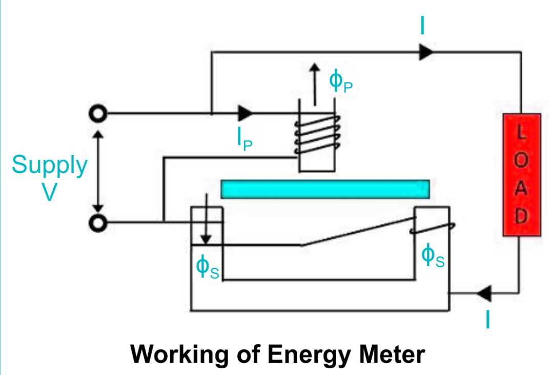
The working principle of an energy meter involves the conversion of electrical energy into mechanical energy or directly into a digital signal. The operating principle differs based on the type of meter used. Here is a basic explanation of the working principles for electromechanical and electronic energy meters:
- Electromechanical Energy Meter:
- Electromagnetic Induction: The core working principle of electromechanical meters is electromagnetic induction. When current flows through a conductor placed in a magnetic field, it experiences a force that makes it move. In an energy meter, the current-carrying coil is placed in the magnetic field created by a permanent magnet or another coil, causing a rotating disc.
- Rotation of Disc: The speed at which the disc rotates is proportional to the power consumed. This rotation is mechanically linked to the dials or counters that indicate the energy usage.
- Friction Brake: A brake mechanism is applied to the disc to limit its speed, ensuring that it does not rotate too quickly, and the readings remain accurate.
- Electronic Energy Meter:
- Voltage and Current Sensing: Electronic meters use voltage and current sensors to continuously measure the electrical parameters of the system.
- Digital Conversion: The measured analog signals (voltage and current) are fed into an analog-to-digital converter (ADC) that transforms the continuous signals into discrete digital signals.
- Microcontroller Processing: A microcontroller processes the digital signals, calculating the energy consumed in real-time. The calculated data is shown on a digital display and saved for later reference.
Construction of an Energy Meter
The construction of an energy meter can vary depending on the type (electromechanical, electronic, or smart). However, the general components include the following:
- Current Coil: This coil is placed in series with the load and carries the current to be measured. It generates a magnetic field that interacts with the magnetic field of the voltage coil, producing a mechanical torque in the case of electromechanical meters.
- Voltage Coil: The voltage coil produces a magnetic field that interacts with the one created by the current coil. The voltage coil generates a magnetic field that interacts with the magnetic field produced by the current coil.
- Rotating Disc (for electromechanical meters): The current and voltage coils generate a magnetic field that induces a torque on a metal disc. The disc rotates, and the speed of rotation is proportional to the power consumption. The mechanical motion of the disc drives the dials to display the energy used.
- Digital Display (for electronic meters): Instead of mechanical dials, electronic energy meters have a digital display that shows the energy consumption in numerical form. A microcontroller processes the data to update the display in real-time.
- Mechanical Dials: In older electromechanical meters, the disc’s motion is linked to a set of dials or gears that indicate the energy usage.
- Brake Mechanism: A friction brake mechanism is applied to slow down the rotation of the disc in electromechanical meters, ensuring the meter measures the energy consumption accurately.
- Transformer (optional): In some energy meters, especially for higher voltage systems, transformers are used to step down the voltage to safe, measurable levels.
Energy Meter Phasor Diagram
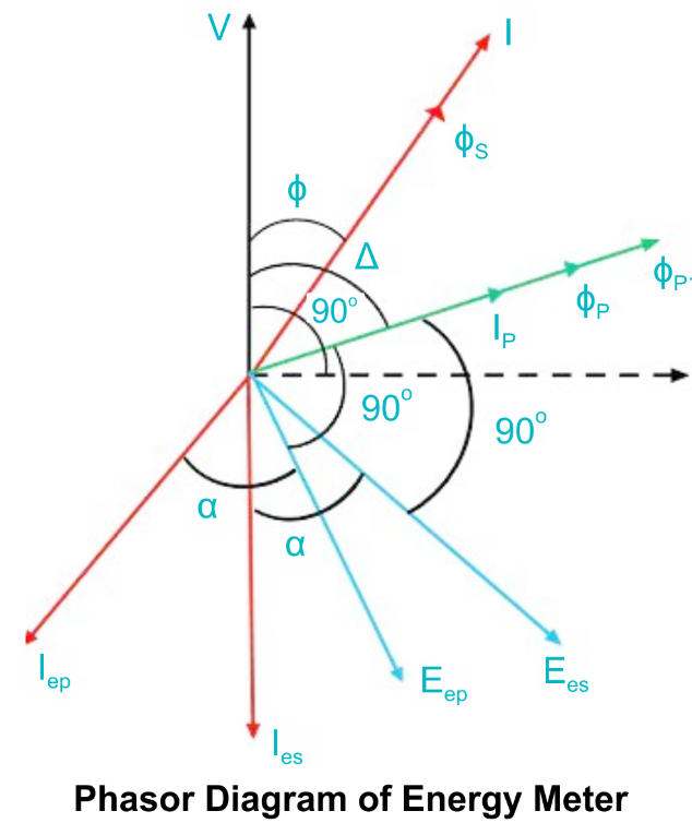
The phasor diagram is a graphical representation of the relationship between the voltage and current waveforms in an AC circuit. For energy meters, phasor diagrams help in understanding how the current and voltage are related, which is essential for accurate energy measurement.
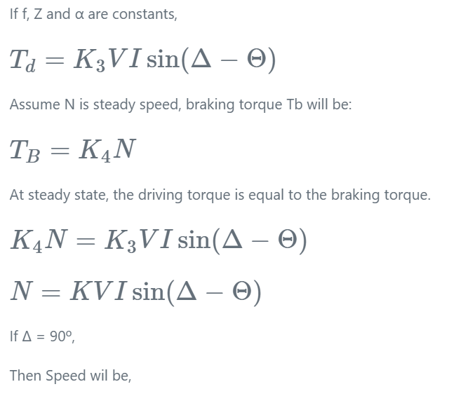
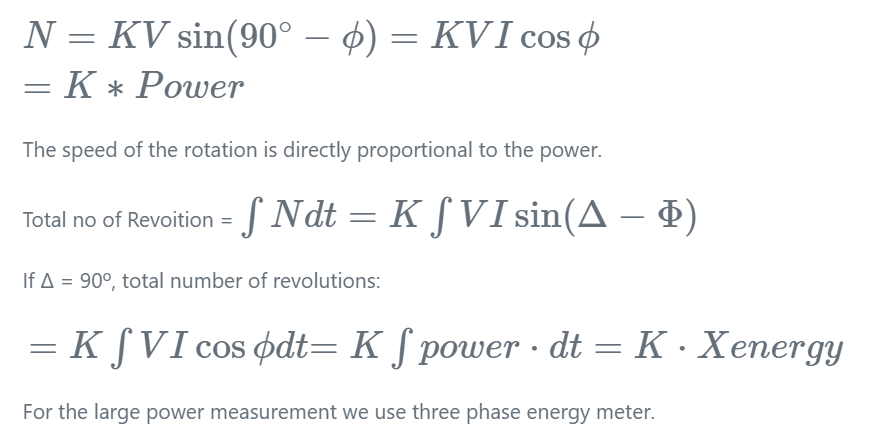
In a typical AC circuit, the voltage and current waveforms are sinusoidal but may be out of phase. The angle between the voltage and current phasors indicates the phase difference. For active power (real power), the voltage and current are in phase, and the power factor is unity (1). However, in most practical cases, the current and voltage are not perfectly in phase due to inductive or capacitive components, leading to a power factor less than 1.
The energy meter measures the product of voltage and current over time, which is then displayed as the energy consumption. The phase difference between the current and voltage is critical, as it influences the calculation of the true power (active power) that the energy meter records.
Conclusion
Energy meters are indispensable tools in modern electrical systems, providing accurate measurement and monitoring of electrical energy usage. Whether electromechanical, electronic, or smart meters, they all serve the primary function of measuring electrical consumption. Understanding the construction, working principles, and types of energy meters helps consumers and utilities optimize energy management and ensure efficient billing practices. Phasor diagrams are a useful tool in understanding the relationship between voltage and current, aiding in accurate energy measurement, particularly in AC circuits.
The post Energy Meter Definition, Types, Working, Construction & Diagram appeared first on ELE Times.
Analog IC vs Digital IC – Difference and Comparison
Integrated circuits (ICs) have revolutionized modern electronics, serving as the backbone of countless devices. Broadly, ICs are categorized into two main types: Analog ICs and Digital ICs. Understanding their differences and specific applications is essential for selecting the right components for various electronic systems. This article delves into the distinctions and comparisons between analog and digital ICs, highlighting their respective advantages, limitations, and use cases.
What are Analog ICs?
Analog ICs process continuous signals that vary over time and are used to manage real-world data such as sound, light, temperature, or pressure. These integrated circuits are crucial in scenarios that demand high precision and uncompromised signal quality.
Key Features of Analog ICs:
- Continuous Signal Processing: Operate with signals that have infinite values within a range.
- Signal Amplification and Conditioning: Amplify or modify analog signals for further processing.
- High Sensitivity: Analog ICs are ideal for handling small changes in signal amplitude.
Common Examples:
- Operational amplifiers (op-amps)
- Voltage regulators
- Analog-to-digital converters (ADCs)
- Audio amplifiers
What are Digital ICs?
Digital integrated circuits process discrete signals, encoding information in binary format, where data is represented as sequences of 0s and 1s. These ICs are integral to modern computing and communication systems.
Key Features of Digital ICs:
- Binary Signal Processing: Work with two distinct states, high (1) and low (0).
- Logical Operations: Perform arithmetic, logical, and control operations efficiently.
- Noise Immunity: Digital ICs demonstrate greater resilience to noise, making them more reliable in environments with high interference.
Common Examples:
- Microprocessors
- Memory chips (RAM, ROM)
- Logic gates
- Digital-to-analog converters (DACs)
Comparison Between Analog ICs and Digital ICs
| Aspect | Analog IC | Digital IC |
| Signal Type | Continuous signals | Discrete signals (binary) |
| Processing | Processes real-world, variable data | Processes binary data |
| Complexity | Simpler design | Higher complexity in circuits |
| Noise Sensitivity | More vulnerable to interference and distortions | More resistant to interference and noise disruptions |
| Applications | Audio, sensors, signal conditioning | Computing, storage, digital communication |
| Power Consumption | Generally higher for amplifiers | Lower for logic circuits |
| Accuracy | Depends on precision of components | High for binary operations |
| Speed | Limited by signal amplitude and frequency | Faster due to digital switching |
Hybrid ICs: Bridging the Gap
Modern systems often necessitate a combination of both analog and digital capabilities to function seamlessly. For instance, smartphones rely on analog ICs for signal acquisition (microphones, cameras) and digital ICs for processing (processors, memory). Hybrid ICs, which combine analog and digital components, are increasingly popular for such integrated applications.
Example:
- Analog-to-Digital Converters (ADCs) convert continuous analog inputs into a digital format, enabling their use in computational and processing systems.
- Digital-to-Analog Converters (DACs) take processed digital data and convert it back into analog signals for practical, real-world output.
Applications of Analog ICs
- Audio Equipment: Analog amplifiers and equalizers enhance sound quality in audio systems.
- Power Management: Voltage regulators and power amplifiers manage and stabilize power supplies.
- Sensors and Instrumentation: Analog ICs process data from temperature, pressure, and motion sensors.
Applications of Digital ICs
- Computing Devices: Microprocessors and memory chips drive computers and smartphones.
- Communication Systems: Digital signal processors (DSPs) enable data encoding, modulation, and transmission.
- Automation and Control: Logic circuits and microcontrollers power robotics and industrial automation.
Advantages and Disadvantages
Analog ICs:
- Advantages:
- Superior for real-world signal processing.
- Ideal for use in scenarios where maintaining high signal accuracy and integrity is essential.
- Disadvantages:
- More susceptible to interference and signal degradation.
- Larger power consumption for certain tasks.
Digital ICs:
- Advantages:
- High accuracy and noise immunity.
- Efficient for high-speed operations and complex computations.
- Disadvantages:
- Limited in handling real-world signals directly.
- Conversion to and from analog signals may introduce delays.
Conclusion
Analog and digital ICs serve distinct yet complementary roles in modern electronics. While analog ICs excel in processing real-world signals with precision, digital ICs dominate areas requiring speed, accuracy, and computational power. The synergy of these technologies, often realized in hybrid ICs, is driving innovation across industries such as healthcare, automotive, consumer electronics, and communication. Understanding the strengths and limitations of each type enables engineers and designers to create optimized and efficient electronic systems tailored to specific applications.
The post Analog IC vs Digital IC – Difference and Comparison appeared first on ELE Times.
NUBURU announces board and committee appointments
Voyant launches FMCW LiDAR sensor on a chip
DOE announces $179m funding for Microelectronics Science Research Centers
University of Glasgow appoints research associate to lead KTP with Vector Photonics
TRUMPF introduces 760nm and 763nm VCSELs for spectroscopic oxygen sensing
GlobalFoundries unveils GF Labs to accelerate technology innovation
Gallium Semiconductor opens Nijmegen R&D Center
DoD awards GlobalFoundries $117m to transfer 45nm SOI from East Fishkill to fab in Malta, NY
HG adds Wide Yield as new strategic investor
Nexperia and KYOCERA AVX partner on GaN automotive power modules
Siemens collaborates with GlobalFoundries to provide silicon photonics design verification
Sivers Photonics wins $617,000 initial order to supply laser sources
NREL raises one-sun solar cell efficiency record to 39.5%
Cubic-phase III-nitride LEDs overcome efficiency droop
Rio Tinto starts tellurium production at Kennecott
Navitas’ revenue grows by 8.2% in Q1
Scout Clean Energy orders 378MW of First Solar’s PV modules
Aixtron to supply CCS 3x2 MOCVD system to Boise State University
Pages

