
Feed aggregator
STMicroelectronics recognized as a Global Top Employer 2025
- STMicroelectronics has been awarded “Top Employer Global” certification for the first time
- 17 companies in the world have obtained this international certification for 2025
- ST entities in 41 countries certified as Top Employer
STMicroelectronics, a global semiconductor leader serving customers across the spectrum of electronics applications, has been recognized for the first time as a global Top Employer for 2025 by Top Employers Institute.
This year STMicroelectronics was one of only 17 global Top Employers to be recognized by Top Employers Institute for their outstanding HR policies and practices worldwide, covering ST entities in 41 countries. The Top Employers Institute program certifies organizations based on the participation and results of their HR Best Practices Survey. STMicroelectronics was distinguished in this ranking thanks to a continuous improvement approach and stands out particularly in the themes of Ethics & Integrity, Purpose & Values, Organization & Change, Business Strategy, and Performance.
“A couple of years ago, we began a people-centric transformation to enhance our leadership culture, simplify and digitalize people processes, with the employee journey and experience as our north star. Achieving the Top Employer Global certification confirms that our efforts are well-directed, and that ST is a place where every talent can thrive, regardless of their career stage or perspective,” said Rajita D’Souza, President, Human Resources & Corporate Social Responsibility, STMicroelectronics.
“We’re excited that STMicroelectronics certified as a global Top Employer for the first time. They have particularly showcased their strengths in areas such as Organisation & Change, Ethics & Integrity, Purpose & Values and Business Strategy. This Certification shows ST’s commitment to creating a better world of work through their HR initiatives and practices, by demonstrating how they support their colleagues across 41 countries,” said David Plink, CEO Top Employers Institute.
The Top Employers Institute survey, followed by validation and audit, covers six HR domains consisting of 20 topics including People Strategy, Work Environment, Talent Acquisition, Learning, Diversity & Inclusion, Wellbeing and more. The program has certified and recognized over 2,400 Top Employers in 125 countries/regions across five continents.
The post STMicroelectronics recognized as a Global Top Employer 2025 appeared first on ELE Times.
X-CUBE-MCSDK 6.3.2: HSO, ZeST, GUI, or why motor control has never been more accessible
Author: STMicroelectronics
As ST recently released X-CUBE-MCSDK 6.3.2, let us delve into its firmware libraries and its Graphical User Interface (GUI) to see how it can help create motor control applications. Designed for permanent magnet synchronous (PMSM) and BLDC motors using FOC (Field-oriented control) or 6-steps, it has gained popularity since we launched it in 2018 because it helps engineers bring their solutions to market faster. For instance, the algorithms from ST will maximize efficiency and facilitate the implementation of critical features like on-the-fly startup for air conditioning fans, a single shunt for cost-effective solutions, flux weakening for washing machines, and a rotor’s angular position detection for sensorless applications.
X-CUBE-MCSDK: Latest highlights HSOOver the years, X-CUBE-MCSDK has received new algorithms that have changed what is capable on BLDC motors and PMSM, such as HSO or high-sensitivity observer. In a nutshell, HSO is a field-oriented control algorithm that enables an application to figure out the rotor’s position and speed without needing a sensor. It’s particularly useful with PMSM sensorless motors running at low speeds in home appliances, for instance, because cost is such a critical factor. To attract new customers, manufacturers must lower their bill of materials, which means doing away with sensors and using more cost-effective MCUs, like an STM32G4. By using HSO, engineers can meet those constraints.
ZeSTZeST (zero-speed full torque) is another algorithm meant to optimize the operations of sensorless motors by enabling them to recover from a complete stop. Combined with HSO, it can detect when a motor is no longer rotating and immediately resume operations. Accordingly, since most applications don’t need to know if a motor has ceased turning, most developers will only need to use HSO, which has been available in X-CUBE-SDK since version 6.2. However, engineers working on applications that could use ZeST can reach out to their local ST representative and seek to enable the STM32 ZeST and implement the feature in their application.
The idea behind HSO and ZeST isn’t new, and more seasoned engineers will be familiar with the phase-locked loop (PLL) observer, a technique (also found in X-CUBE-MCSDK) that determines the rotor position and speed without a sensor. However, combining HSO and ZeST helps alleviate some of PLL’s shortcomings, such as its inability to work under a minimum motor speed. Additionally, HSO and ZeST take advantage of the STM32G4 to run without maximizing CPU usage, despite how advanced these algorithms are. HSO and ZeST also have a shorter start-up time and do not generate high peak current, resulting in an energy saving between 15% and 40% in a typical washing machine application.
Regular updatesX-CUBE-MCSDK receives regular updates. Before version 6.3.1 in September 2024, we launched version 6.3 in May 2024, which brought support for new MCUs, like the STM32C0, our new entry-level device, and new STSPIN32 devices like the STSPIN32G4. It also added a new Board Designer tool and the ability to spec user boards using JSON to simplify developments. And while all versions of X-CUBE-MCSDK are mindful of legacy support, previous versions have also brought new features like BLCD six-step motors, monitoring, and profiling. Put simply, X-CUBE-MCSDK is a unique way to create motor control applications because it demystifies complex notions and makes modern algorithms and development paradigms more accessible.
X-CUBE-MCSDK and its robust firmware architecture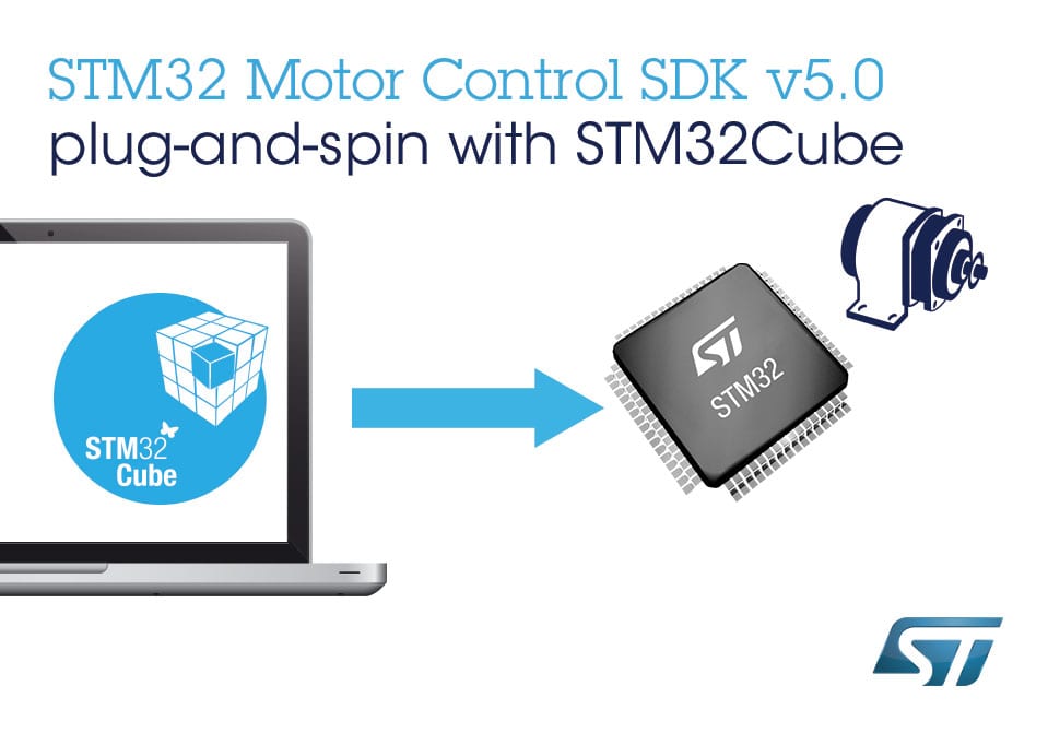 Motor Control Libraries now based on STM32Cube
A significant advantage of the new SDK resides in the use of a different programming paradigm to ensure developers get a code that is a lot easier to customize and debug. Before X-CUBE-MCSDK, certain aspects of our libraries used object-oriented concepts inherited from C++. We rewrote them to something more approachable in C to simplify application development. For example, we no longer cast some expressions to void, a popular method in C++ to suppress compiler warnings, but that tends to complicate debugging operations drastically. Porting libraries to C also helped optimize applications as teams can more easily improve performance and efficiency.
X-CUBE-MCSDK was thus a major internal overhaul accompanied by massive updates to our SDK’s libraries. Indeed, previous versions used older code that was no longer standard on STM32 MCUs. STM32Cube is the de facto solution for all developments on our microcontrollers. It offers Hardware Abstraction Layers (HAL), increases portability between STM32 MCUs, and offers low-level APIs, drivers, and other Middleware components to make the ST ecosystem more accessible and efficient. X-CUBE-MCSDK brought the same standard libraries, so developers familiar with STM32Cube could have a much easier time with the code and reuse a significant chunk of their application from one project to the next.
X-CUBE-MCSDK and its flexible GUI Interface of STM32CubeMX
Aside from internal modifications that may not always be obvious, the new SDK works in conjunction with STM32CubeMX. Indeed, X-CUBE-MCSDK still uses MC-Workbench, a graphical tool where engineers can enter their motor and sensors’ parameters to generate custom code for their setup. When developers want to change the preselected configuration, such as the STM32 part number, the pinout configuration, the clock configuration, or add peripherals for new communication interfaces, they can more easily generate a new code for their application by using STM32CubeMX. They are also free to customize projects and add custom code (extra PID control loop, for instance) within tags created by STM32CubeMX.
The ST Community is fond of the STM32CubeMX configuration tool because it uses STM32Cube libraries and an intuitive interface to quickly generate header files, taking complex design operations out of developers’ hands. Using a step-by-step process, it’s easy to configure pinouts, clock trees, and peripherals, as well as resolve conflicts, among other things. If designers working on a motor control application decide to use another MCU in the middle of their prototyping phase, they will merely need to open STM32CubeMX, and will much more quickly port the work done on the previous MCU. X-CUBE-MCSDK thus brought a new level of flexibility.
ST teams are already working on the next updates. In the meantime, the best way to start working on a motor control solution is to check out our dedicated Wiki and ask questions on our Community forum. The Wiki will guide users by showing them how to run example applications on ST development boards to hasten prototyping. It’s also a quick way to see how we implemented our libraries and can thus serve as the basis for a project. For instance, the page on the six-step algorithm helps engineers with less experience understand what is happening while also providing a walkthrough of the GUI and compatible boards.
The post X-CUBE-MCSDK 6.3.2: HSO, ZeST, GUI, or why motor control has never been more accessible appeared first on ELE Times.
100-V MOSFETs cut on-resistance

Renesas 100-V N-channel MOSFETs leverage an improved wafer manufacturing process with split gate technology, reducing on-resistance (RDS(on)) by 30%. The REXFET-1 process also cuts total gate charge (Qg) by 10% and gate-to-drain charge (Qgd) by 40%, according to the company.

Designed for high-power applications, these MOSFETs provide high-current switching in motor control, battery management systems, power management, and charging. Typical end products include electric vehicles, e-bikes, charging stations, power tools, and uninterruptible power supplies.
Both the RBA300N10EANS and RBA300N10EHPF MOSFETs feature a standard gate drive voltage of 2.0 V to 4.0 V. Other key specifications include an RDS(on) of 1.5 mΩ, drain current (ID) of 340 A, Qg of 170 nC, and Qgd of 30 nC.
In addition to enhanced electrical characteristics, the RBA300N10EANS and RBA300N10EHPF MOSFETs are offered in TOLL and TOLG packages, respectively. These packages are pin-compatible with devices from other manufacturers and 50% smaller than conventional TO-263 packages. The TOLL package also has wettable flanks for optical inspection.
The RBA300N10EANS and RBA300N10EHPF MOSFETs are now available in production volumes. Renesas also offers a reference design and application note to help shorten design cycles.
Find more datasheets on products like this one at Datasheets.com, searchable by category, part #, description, manufacturer, and more.
The post 100-V MOSFETs cut on-resistance appeared first on EDN.
Reference design highlights GaN for motor drives

EPC offers a GaN-based motor drive inverter reference design for industrial and battery-powered applications. The EPC91200 demonstration board, built for 3-phase brushless DC motors, integrates the EPC2305, a 150-V, 3.0-mΩ GaN FET.

With a wide input voltage range of 30 V to 130 V, the EPC91200 supports 80-V and 110-V battery systems in industrial automation and material handling equipment. It delivers up to 40 ARMS (60 A pk) of output current and operates at PWM switching frequencies up to 150 kHz, demonstrating GaN technology’s efficiency, reliability, and adaptability in power systems.
An optimized PCB layout and GaN technology minimize resistance and heat generation, enhancing performance. The 130×100-mm demo board features current sensing, voltage monitoring, overcurrent protection, and temperature sensing. It also includes a preconfigured shaft encoder/Hall sensor interface and supports field-oriented control. Compatible with various controller boards from STMicroelectronics, Texas Instruments, and Microchip, the EPC91200 offers broad integration flexibility.
The EPC91200 reference design board costs $812.50 and is available from Digi-Key.
Find more datasheets on products like this one at Datasheets.com, searchable by category, part #, description, manufacturer, and more.
The post Reference design highlights GaN for motor drives appeared first on EDN.
GaN RF switch delivers 20 W

Built on a wide-bandgap GaN HEMT process, Teledyne’s TDSW84230EP reflective SPDT switch covers 30 MHz to 5 GHz, handling 20 W of continuous power. It is intended to replace PIN diode-based RF switches commonly used in the RF front ends of tactical and military communication radios.

The TDSW84230EP tolerates up to 900 mA/mm of saturation current, leveraging GaN’s high breakdown voltage and carrier density. Encased in a compact 3×3×0.8-mm, 16-pin QFN package, it offers 0.2-dB insertion loss and 45-dB port isolation, providing enhanced efficiency and saving board space over PIN diode architectures.
Qualified for operation over the military temperature range of -55°C to +125°C, the TDSW84230EP requires a positive supply voltage of 2.6 V to 5.25 V. Its internal charge pump is disabled to eliminate charge pump spurs in low-noise applications, while a -18-V supply is needed on the VCP pin.
The TDSW84230EP GaN RF switch is available now in commercial versions from Teledyne HiRel and authorized distributors.
Find more datasheets on products like this one at Datasheets.com, searchable by category, part #, description, manufacturer, and more.
The post GaN RF switch delivers 20 W appeared first on EDN.
Murata introduces ultra-small chip inductor

At this month’s CES 2025 show, Murata unveiled what is claimed to be the world’s smallest 006003-inch (0.16×0.08 mm) chip inductor. This development offers a 75% volume reduction compared to the previous smallest product, the 008004-inch (0.25×0.125 mm) inductor.

“Following our success in introducing the world’s smallest multilayer ceramic capacitor (MLCC) in September 2024, our engineering teams are now developing a pioneering 006003-inch size chip inductor to further meet market demands,” says Takaomi Toi, general manager of Inductor Product Development at Murata Manufacturing.
“With the creation of the world’s smallest class prototype, we’re confident that this product represents an exciting addition to Murata’s extensive portfolio of market-leading chip inductors. This development continues to demonstrate Murata’s commitment to innovation and also marks a significant milestone in our quest to support the miniaturization and enhanced functionality of future electronic devices,” Toi said.
For more information about this chip inductor development, please contact Murata here.
Find more datasheets on products like this one at Datasheets.com, searchable by category, part #, description, manufacturer, and more.
The post Murata introduces ultra-small chip inductor appeared first on EDN.
EDA tool tackles 3D IC design challenges

GENIO EVO, an integrated chiplet/package EDA tool from MZ Technologies, addresses thermal and mechanical stress in the pre-layout stage of 3D IC design. Set to be demonstrated at this month’s Chiplet Summit, GENIO EVO is the second generation of MZ’s flagship GENIO cross-fabric platform for system design. Like its predecessor, GENIO EVO enables co-design of chiplets, dies, silicon interposers, packages, and surrounding PCBs to meet area, power, and performance targets.

GENIO EVO integrates seamlessly with existing commercial implementation platforms or custom EDA flows through plugins. Operating at the architectural level, it provides optimal system choices for 2.5D or 3D multi-die designs. A new user interface supports a cross-hierarchical, 3D-aware design methodology that streamlines the system design process. By integrating IC and advanced packaging design, it ensures full system-level optimization, shorter design cycles, faster time-to-manufacturing, and improved yields.

The platform identifies and analyzes thermal and mechanical failures. It supports architectural exploration and what-if analysis in the early design stages to improve implementation predictability. By planning and managing high-pin-count interconnects in complex multi-fabric designs, it anticipates and avoids downstream thermal and mechanical issues.
GENIO EVO is available for immediate licensing. For more information, click the link below.
Find more datasheets on products like this one at Datasheets.com, searchable by category, part #, description, manufacturer, and more.
The post EDA tool tackles 3D IC design challenges appeared first on EDN.
Guerrilla RF unveils new GaN-on-SiC HEMT power amplifiers dice for high-performance RF
Add one resistor to allow DAC control of switching regulator output

Whether its buck, boost, or buck/boost, internal or external switch, milliamps or tens of amps, a literal cornucopia of programmable output switching regulator/converter chips are commercially available. While the required external Ls and Cs (of course) vary wildly from topology to topology and chip to chip, (almost) all use exactly the same basic two-resistor network for output voltage programming shown in Figure 1. Its example buck type regulator was picked more or less arbitrarily, so please ignore the L and Cs and just focus on R1, R2, and (later) R3.
 Figure 1 The (almost) universal regulator output programming network where Vout = Vsense(R1/R2 + 1) = 0.8v*(11.5 + 1) = 10v.
Wow the engineering world with your unique design: Design Ideas Submission Guide
For reasons known only to gurus of the mystic and marvelous monolithic realm, the precision Vsense feedback node voltage varies from type to type over a roughly 3:1 range from 0.50v to 1.5v. Recommended values for R1 vary too.
The point is the topology doesn’t vary. All (or at least most) conform faithfully to Figure 1. This surprising uniformity becomes very useful if your application requires DAC control of the output voltage. See Figure 2 for how this can be done with a positive polarity DAC and just one added resistor: R3.

Figure 2 Regulator output programming with a DAC and the KISS1 network where Vout = (Vc)*(R1/R2) = (2.5 to 0v) 4 = 0 to 10v.
Given reasonable choices for the DAC (e.g., 2.5v), numbers for R1 and Vsense from the regulator chip datasheet, and Vomax from your application requirements, here’s the KISS1 arithmetic:
- R2 = R1 Vcmax/Vomax
- R3 = R1/(Vomax/Vsense – R1/R2 – 1)
And, in the grand tradition of the KISS1 principle, that’s it. Ok, ok. Except maybe for a couple of (minor?) caveats. For example:
- Expression 2 above, and therefore the necessary value for R3, must shake out positive. I can’t think of a practical case where it wouldn’t, but there’s probably some perverse permutation of parameters out there where it won’t, and implementing negative resistors isn’t particularly simple.
- The relation between Vout and Vc is inverse. So, the digital version of Vc must be 1’s complemented (a totally KISS-bit of software arithmetic to flip all the bits, so 0s become 1s, and 1s become 0s) before being written to the DAC register.
- Vin must be adequate for the chosen chip to generate the chosen Vomax when Vc = 0. Duh.
So maybe it’s not really totally KISS1, just mostly.
1 Famous KISS principle: Is a footnote really necessary?
Stephen Woodward’s relationship with EDN’s DI column goes back quite a long way. Over 100 submissions have been accepted since his first contribution back in 1974.
Related Content
- PWM power DAC incorporates an LM317
- Parsing PWM (DAC) performance: Part 2—Rail-to-rail outputs
- Precision DC motor speed control via pot or DAC
- Designing with a DAC: Settle for the best
The post Add one resistor to allow DAC control of switching regulator output appeared first on EDN.
METLEN investing €295.5m in bauxite, alumina and gallium production in Greece
Pages

