
Feed aggregator
RTD vs Thermocouple vs Thermistor: Understanding Temperature Sensors
Temperature sensors are critical components in a variety of industries, from manufacturing and automotive to healthcare and environmental monitoring. Among the most common temperature-sensing devices are Resistance Temperature Detectors (RTDs), thermocouples, and thermistors. Each of these sensors has unique characteristics, advantages, and limitations, making them suitable for different applications. This article provides a detailed comparison to help you choose the right sensor for your needs.
- Resistance Temperature Detectors (RTDs)
RTDs measure temperature by correlating the resistance of a material (usually platinum) to temperature. Platinum is preferred because of its stability and linear resistance-temperature relationship.
Key Features of RTDs:
- Accuracy: RTDs deliver exceptional precision, typically within ±0.1°C.
- Stability: They provide outstanding consistency and reliable performance over long durations.
- Temperature Range: Commonly operate effectively between -200°C and 600°C.
- Linearity: RTDs exhibit a near-linear relationship between resistance and temperature, simplifying data interpretation.
Advantages:
- Highly precise and reliable.
- Extended operational life with negligible performance degradation over time.
- Suitable for industrial and laboratory settings.
Limitations:
- Expensive compared to thermocouples and thermistors.
- Fragile and sensitive to physical shocks and vibrations.
- Requires external circuitry for resistance measurement.
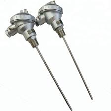
- Thermocouples
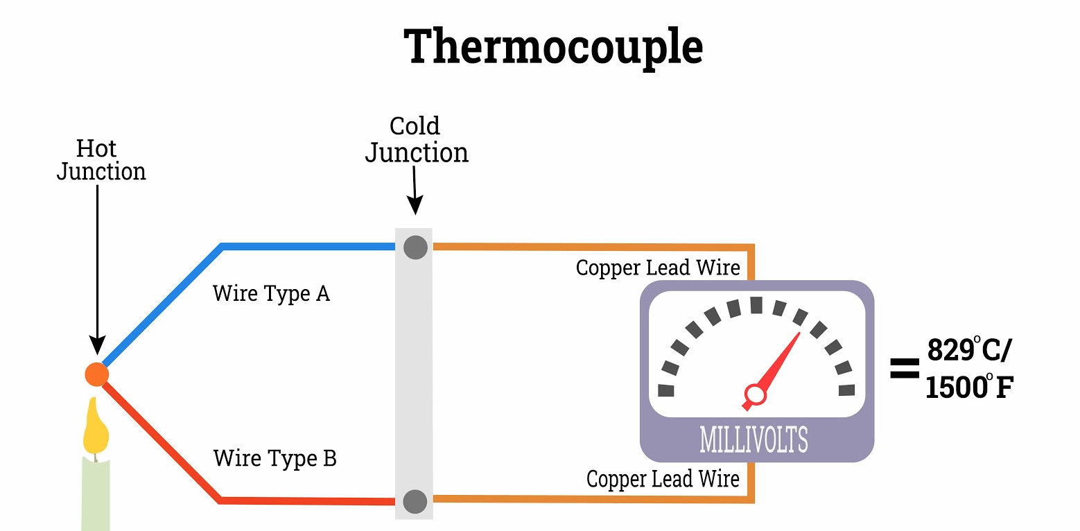
Thermocouples generate an electrical voltage that reflects the temperature gradient between two dissimilar metal junctions and a reference point. The voltage generated is interpreted to identify the corresponding temperature.
Key Features of Thermocouples:
- Versatility: Available in various types (e.g., Type J, K, T, E) to suit specific applications.
- Temperature Range: Capable of measuring temperatures from -200°C to over 2000°C, depending on the type.
- Durability: Resistant to mechanical stress and high temperatures.
Advantages:
- Wide temperature range.
- Cost-effective, especially for high-temperature applications.
- Their rapid response is attributed to a low thermal mass, enabling quick detection of temperature changes.
Limitations:
- Less accurate than RTDs, with typical errors of ±2°C to ±5°C.
- Requires regular calibration for precise measurements.
- Voltage signals are small and can be affected by electrical noise.
- Thermistors
Thermistors are temperature-sensitive resistors made from ceramic or polymer materials. Their resistance decreases (Negative Temperature Coefficient, NTC) or increases (Positive Temperature Coefficient, PTC) significantly with temperature changes.
Key Features of Thermistors:
- Sensitivity: Extremely sensitive to small temperature changes.
- Temperature Range: Typically operate within -50°C to 150°C.
- Size: Compact and easy to integrate into electronic systems.
Advantages:
- High sensitivity enables precise detection of small temperature changes.
- Low cost and compact design.
- Quick response time.
Limitations:
- Limited temperature range.
- Non-linear response, requiring complex calibration.
- Thermistors tend to have lower durability in extreme or harsh environments when compared to RTDs and thermocouples.
Comparison Table
| Feature | RTD | Thermistor | Thermocouple |
| Accuracy | High (±0.1°C) | High in a limited range | Moderate (±2°C to ±5°C) |
| Temperature Range | -200°C to 600°C | -50°C to 150°C | -200°C to 2000°C |
| Durability | Fragile | Moderate | Highly durable |
| Cost | Expensive | Economical | Affordable to mid-range |
| Response Time | Intermediate | Quick | Rapid |
| Linearity | Near-linear | Non-linear | Non-linear |
Choosing the Right Sensor
Selecting a temperature sensor hinges on its intended use:
- RTDs: Preferred for applications needing high precision and consistent performance, such as in labs, industrial setups, and HVAC systems.
- Thermocouples: Well-suited for high-temperature or challenging environments, including metal forging, kilns, and aviation.
- Thermistors: Ideal for compact, cost-sensitive applications like household devices, medical instruments, and consumer gadgets.
Conclusion
RTDs, thermocouples, and thermistors are essential tools for temperature measurement, each with distinct strengths and weaknesses. Understanding their characteristics and applications ensures optimal performance and cost-efficiency in your projects. Whether you prioritize precision, range, or durability, selecting the appropriate sensor will significantly impact the success of your temperature-sensitive processes.
The post RTD vs Thermocouple vs Thermistor: Understanding Temperature Sensors appeared first on ELE Times.
STMicroelectronics Announces Timing for Fourth Quarter and Full Year 2024 Earnings Release and Conference Call
STMicroelectronics, a global semiconductor leader serving customers across the spectrum of electronics applications, announced that it will release its fourth quarter and full year 2024 earnings before the opening of trading on the European Stock Exchanges on Thursday, January 30, 2025.
The press release will be available immediately after the release on the Company’s website at www.st.com.
STMicroelectronics will conduct a conference call with analysts, investors and reporters to discuss its fourth quarter and full year 2024 financial results and current business outlook on January 30, 2025, at 9:30 a.m. Central European Time (CET) / 3:30 a.m. U.S. Eastern Time (ET).
A live webcast (listen-only mode) of the conference call will be accessible at ST’s website https://investors.st.com and will be available for replay until February 14, 2025.
The post STMicroelectronics Announces Timing for Fourth Quarter and Full Year 2024 Earnings Release and Conference Call appeared first on ELE Times.

Spent the weekend making a logic simulation
 | submitted by /u/flippont [link] [comments] |
ADI’s efforts for a wirelessly upgraded software-defined vehicle
In-vehicle systems have massively grown in complexity with more installed speakers, microphones, cameras, displays, and compute burden to process the necessary information and provide the proper, often time-sensitive output. The unfortunate side effect of this complexity is the massive increase in ECUs and subsequent cabling to and from its allocated subsystem (e.g., engine, powertrain, braking, etc.). The lack of practicality with this approach has become apparent where more OEMs are shifting away from these domain-based architectures and subsequently traditional automotive buses such as local interconnect network (LIN), controlled area network (CAN) for ECU communications, FlexRay for x-by-wire systems, and media oriented transport (MOST) for audio and video systems. SDVs rethink underlying vehicle architecture so that cars are broken into zones that will directly service the vehicle subsystems that surround it locally, cutting down wiring, latency, and weight. Another major benefit of this are over-the-air (OTA) updates using Wi-Fi or cellular to update cloud-connected cars, however bringing ethernet to the automotive edge comes with its complexities.
ADI’s approach to zonal architecturesThis year at CES, EDN spoke with Yasmine King, VP of automotive cabin experience at Analog Devices (ADI). The company is closely working with the underlying connectivity solutions that allow vehicle manufacturers to shift from domain architectures to zonal with ethernet-to-edge (E2B) bus, automotive audio bus (A2B), and gigabit multimedia serial link (GMSL) technology. “Our focus this year is to show how we are adding intelligence at the edge and bringing the capabilities from bridging the analog of the real world into the digital world. That’s the vision of where automotive wants to get to, they want to be able to create experiences for their customers, whether it’s the driving experience, whether it’s the back seat passenger experience. How do you help create these immersive and safe experiences that are personalized to each occupant in the vehicle? In order to do that, there has to be a fundamental change of what the architecture of the car looks like,” said King. “So in order to do this in a way that is sustainable, for mobility to remain green, remain long battery range, good fuel efficiency, you have to find a way of transporting that data efficiently, and the E2B bus is one of those connectivity solutions where it’s it allows for body control, ambient lighting.”
E2B: Remote control protocol solution 10BASE-T1S solutionBased on the OPEN alliance 10BASE-T1S physical layer (PHY), the E2B bus aims at removing the need for MCUs centralizing the software to the high performance compute (HPC) or central compute (Figure 1). “The E2B bus is the only remote control protocol solution available on the market today for the 10BASE-T1S so it’s a very strong position for us. We just released our first product in June of this past year, and we see this as a very fundamental way to help the industry transform to zonal architecture. We’re working with the OPEN alliance to be part of that remote control definition.” These transceivers will integrate low complexity ethernet (LCE) hardware for remote operation and, naturally, can be used on the same bus as any other 10BASE-T1S-compliant product
BMW has already adopted the E2B bus for their ambient lighting system, King mentioned that there has already been further adoption by other OEMs but they were not public yet. “The E2B bus is one of those connectivity solutions where it allows for body control, ambient lighting. Honestly, there’s about 50 or 60 different applications inside the vehicle.” She mentioned how E2B is often used for ambient lighting today but there are many other potential applications such as driver monitoring systems (DMSs) that might detect a sleeping driver via the in-vehicle biometric capabilities to then respond with a series of measures to wake them up, E2B allows OEMs to apply these measures with an OTA update. Without E2B, you’d have to not only update the DMS, but you’d have to update the multiple nodes that are controlling the ambient light. The owner might have to take it back into the shop to apply the updates, it just takes longer and is more of a hassle. With E2B, it’s a single OTA update that is an easy, quick download to add safety features so it’s more realistic to get that safer, more immersive driver experience.” The goal for ADI is to move all the software from all edge nodes to the central location for updates.

Figure 1: EDN editor, Aalyia Shaukat (left) and VP of automotive cabin experience, Yasmine King (right) in front of a suspension control demo with 4 edge nodes sensing the location of the weighted ball, sends the information back to the HPC to send commands back to control the motors.
A2B: Audio system based on 100BASE-T1Based upon the 100BASE-T1 standard, the A2B audio follows a similar concept of connecting edge nodes with a specialization in sound limiting the installation of weighty shielded analog cables going to and from the many speakers and microphones in vehicles today for modern functions such as active noise cancellation (ANC) and road noise cancellation (RNC). “We have RNC algorithms that are connected through A2B, and it’s a very low latency, highly deterministic bus. It allows you to get the inputs from, say, the wheel base, where you’re listening for the noise, to the brain of the central compute very quickly.” King mentioned how audio systems require extremely low latencies for an enhanced user experience, “your ears are very susceptible to any small latency or distortion.” The technology has more maturity than the newer E2B bus and has therefore seen more adoption, “A2B is a technology that is utilized across most OEMs, the top 25 OEMs are all using it and we’ve shipped millions of ICs.” ADI is working on a second iteration of the A2B bus that multiplies the data rate of the previous generation, this is likely due to the maturation of the 1000BASE-T1 standard for automotive applications that is meant to reach 1 Gbps. When asked about the data rate King responded, “I’m not sure exactly what we are publicly stating yet but it will be a multiplier.”
GMSL: Single-wire SerDes display solutionGMSL is the in-vehicle serializer/deserializer (SerDes) video solution that shaves off the significant wiring typically required with camera and subsequent sensor infrastructure (Figure 2). “As you’re moving towards autonomous driving and you want to replace a human with intelligence inside the vehicle, you need additional sensing capabilities along with radar, LiDAR, and cameras to be that perception sensing network. It’s all very high bandwidth and it needs a solution that can be transmitted in a low-cost, lightweight cable.” Following a similar theme as the E2B and A2B audio buses, using a single cable to manage a cluster display or an in-vehicle infotainment (IVI) human-to-machine interface (HMI) minimizes the potential weight issues that could damage range/fuel efficiency. King finished by mentioning one overlooked benefit of lowering the weight of vehicle harnessing “The other piece that often gets missed is it’s very heavy during manufacturing, when you move over 100 pounds within the manufacturing facilities you need different safety protocols. This adds expense and safety concerns for the individuals who have to pick up the harness where now you have to get a machine over to pick up the harness because it’s too heavy.”

Figure 2: GMSL demo aggregating feeds from six cameras into a deserializer board going into a single MIPI port on the Jetson HPC-platform.
Aalyia Shaukat, associate editor at EDN, has worked in the design publishing industry for six years. She holds a Bachelor’s degree in electrical engineering from Rochester Institute of Technology, and has published works in major EE journals as well as trade publications.
Related Content
The post ADI’s efforts for a wirelessly upgraded software-defined vehicle appeared first on EDN.
Happy workbench Wednesday! Today, I wanted to share how terrifying the exhaust fan module of a Keysight/Ixia XGS12 mainframe is.
 | If you’re not careful with this thing, it’ll probably lop off your fingers: https://imgur.com/a/XuLKBF1 [link] [comments] |
PWMpot approximates a Dpot

Digital potentiometers (“Dpots”) are a diverse and useful category of digital/analog components with up to a 10-bit resolution, element resistance from 1k to 1M, and voltage capability up to and beyond ±15v. However, most are limited to 8 bits, monopolar (typically 0v to +5v) signal levels, and 5k to 100k resistances with loose tolerances of ±20 to 30%.
Wow the engineering world with your unique design: Design Ideas Submission Guide
This design idea describes a simple and inexpensive Dpot-like alternative. It has limitations of its own (mainly being restricted to relatively low signal frequencies) but offers useful and occasionally superior performance in areas where actual Dpots tend to fall short. These include parameters like bipolar signal range, terrific differential nonlinearity, tight resistance accuracy, and programmable resolution. See Figure 1.
 Figure 1 PWM drives opposing-phase CMOS switches and RC network to simulate a Dpot
RC ripple filtering limits frequency response to typically tens to hundreds of Hz.
Switch U1b connects wiper node W to node B when PWM = 1, and to A when PWM = 0. Letting the PWM duty factor, P = 0 to 1, and assuming no excessive loading of W:
Vw = P(Vb – Va) + Va
Meanwhile, switch U1a connects W to node A when PWM = 1, and to B when PWM = 0, thus 180o out of phase with U1b. Due to AC coupling, this has no effect on pot DC output, but the phase inversion relative to U1b delivers active ripple attenuation as described in “Cancel PWM DAC ripple with analog subtraction.”
The minimum RC time-constant required to attenuate ripple to no more than 1 least significant bit (lsb) for any given N = number of PWM bits of resolution and Tpwm = PWM period is given by:
RC = Tpwm 2(N/2 – 2)
For example:
for N = 8, Fpwm = 10 kHz
RC = 10 kHz-1*2(8/2 – 2) = 100 µs*22 = 400 µs
The maximum acceptable value for R is dictated by the required Vw voltage accuracy under load. Minimum R is determined by:
- Required resistance accuracy after factoring in the variability of U1b switch Ron: r which is 40 ±40Ω for the HC4053 powered as in Figure 1.
- Required integral nonlinearity (INL) as affected by switch-to-switch Ron variation, which is just 5 Ω for the HC4053 as powered here.
R = 1k to 10k would be a workable range of choices for N = 8-bit resolution. N is programmable.
The net result is the equivalent circuit shown in Figure 2. Note that, unlike a mechanical pot or Dpot, where output resistance varies dramatically with wiper setting, the PWMpot’s output resistance (R +r) is nominally constant and independent of setting.

Figure 2 The PWMpot’s equivalent circuit where r = switch Ron, P = PWM duty factor, and where the ripple filter capacitors are not shown.
Funny footnote: While pondering a name for this idea, I initially thought “PWMpot” was too long and considered making it shorter and catchy-er by dropping the “WM.” But then, after reading the resulting acronym out loud, I decided it was maybe a little too catchy.
And put the “WM” back!
Stephen Woodward’s relationship with EDN’s DI column goes back quite a long way. Over 100 submissions have been accepted since his first contribution back in 1974.
Related Content
- Cancel PWM DAC ripple with analog subtraction
- A faster PWM-based DAC
- Parsing PWM (DAC) performance: Part 1—Mitigating errors
- PWM power DAC incorporates an LM317
- Cancel PWM DAC ripple with analog subtraction but no inverter
- Cancel PWM DAC ripple with analog subtraction—revisited
The post PWMpot approximates a Dpot appeared first on EDN.
Aledia makes available micro-LED technology for immersive AR
Pages


![[link]](https://i.redd.it/1sxqu7225ube1.png)