


Feed aggregator
Робоча група з гендерної рівності
З метою реалізації Плану дій з імплементації принципів ґендерної рівності в практику діяльності Національного технічного університету України «Київський політехнічний інститут імені Ігоря Сікорського» на 2024-2027 роки в університеті створено Робочу групу з гендерної рівності.
Power Tips #158: Using a programmable logic device as an LLC controller

Inductor-inductor-capacitor (LLC) applications that don’t require a closed control loop can benefit from simple and low-cost implementations.
High-power applications that require isolation and prioritize high efficiency often use inductor-inductor-capacitor (LLC) converters in either a half- or full-bridge configuration implemented on the primary side, depending on the voltages and power levels. Synchronous rectification is often mandatory to achieve good efficiency, especially with low output voltages.
When looking for closed-loop LLC controllers, there are various options on the market, which offer features for protection and a precise ±3% regulated output. For open-loop applications that can tolerate an unregulated output of ±10%, many closed-loop controller features aren’t necessary, and it often takes some effort to disable certain functions to get an open-loop design working.
LLC controller featuresThe feature set for an open-loop LLC controller can be divided into mandatory and optional features. Mandatory features include soft start, enable input, over-current protection (OCP) with cycle-by-cycle current limiting (hiccup mode or latch-off), and driving the primary-side power stage. Optional features may include power-good output, over- and under-voltage lockout, and driving the synchronous rectifiers.
The Texas Instruments programmable logic device (TPLD) family can implement these features to achieve a cost-effective solution for open-loop applications. Figure 1 is a block diagram of the TPLD2001-Q1. This device includes various logic blocks, internal oscillators with a clock frequency up to 25MHz, a state machine, and analog comparators, making it a good match for the features that an open-loop LLC controller requires.

Figure 1 This block diagram shows the building blocks available in the TPLD2001-Q1. Source: Texas Instruments
Generating control signals for the power stages is a simple task. For low switching frequencies, designers can use the internal pulse-width modulation (PWM) generators, but higher frequencies require a logic-based approach. One possible implementation is a classical ring buffer built from configurable one-shot blocks, which generate two inverted signals for the primary side and add dead time. Figure 2 shows an implementation that generates the two control signals for the primary side as well as two control signals for driving the synchronous rectifiers on the secondary side, with adjustable dead bands between primary and secondary.

Figure 2 This example implementation generates four output signals with an adjustable dead band, all within a single TPLD2001-Q1. Source: Texas Instruments
In this way, there is no need for a specialized synchronous rectifier controller. To enable synchronous rectification, a comparator channel can measure the primary-side current to enable synchronous rectification as soon as the converter input current rises above a decision threshold.
Figure 3 shows a design example using synchronous rectification without a specialized controller. The use of LMG2104-Q1 integrated half bridges simplifies the TPLD implementation, since these devices take care of the required dead time for the primary side by themselves.

Figure 3 This overview of an example design uses TI’s TPLD2001-Q1 as a controller. Source: Texas Instruments
It is possible to achieve OCP using the internal comparators, which disable switching if the primary-side current gets too large. The amount of available logic gates enables an implementation that does cycle-by-cycle current limiting by skipping cycles if the primary-side current reaches a set limit (Figure 4). After a certain period of time, the control logic then enters hiccup mode or latch-off, which either one-shots or one of the TPLD’s counters can easily implement. Also, during soft start, the disabled synchronous rectification ensures that no unwanted current flows from the output back to the input of the converter.

Figure 4 This example current-limit implementation also fits within the TPLD2001-Q1. Source: Texas Instruments
An enable input completes the connectivity requirements and resets the device so that it goes through soft start when enabled. For devices with several analog inputs, it is easy to add under-voltage lockout and over-temperature protection features.
Of course, there are some limitations to these programmable logic devices, although many are easy to overcome. When using the internal PWM generators, the maximum frequency is limited to <100 kHz because of the fixed-period counter value.
Because the open-loop LLC topology requires no duty cycle or frequency variation, you can build your own control signal generator using the available logic cells within the TPLD2001-Q1 to achieve your desired output frequency. A 25 MHz clock frequency is high enough to generate suitable dead times and output signal frequencies up to about 500 kHz. Higher frequencies are possible; however, the dead time becomes an increasing percentage of the total switching cycle, thereby lowering efficiency.
When using synchronous rectifier controllers and integrated power stages – which take care of the dead time by themselves – this efficiency penalty is no longer an issue. Figure 5 shows the switching waveform of the design example, using a TPLD for controlling the primary side and synchronous rectification.

Figure 5 This graph from the design example shows the switch node and current waveform. Source: Texas Instruments
If you don’t need more than two analog inputs, a smaller device such as the TPLD1202-Q1 is an option. But since that device has only one comparator, the inputs are multiplexed and therefore too slow for OCP. The discrete analog comparators available within the TPLD2001-Q1 are fast enough to implement OCP and can be used for other features like the previously described simple synchronous rectification control. If OCP is the only analog feature that you require, the smaller TPLD1202-Q1 device variant may be a good fit for more cost-sensitive applications.
ConclusionThe TPLD family offers enough flexibility to implement relatively complex control mechanisms for power converters. LLC applications that don’t require a closed control loop can benefit from a simple and low-cost implementation. Although this power tip is based on a working solution, depending on the overall requirements (for example, bidirectional operation or higher switching frequencies), some device limitations could demand a different approach. Here, the TI MSPM0 microcontroller could become a valid option.

As part of the Power Design Services team, Björn Görner has eight years of experience designing custom power solutions and reference designs, with the main focus on automotive applications. He is a regular presenter for Power Supply Design Seminars, which Texas Instruments offers biannually to educate and support anyone interested in power conversion.
Related Content
- Power Tips #155: How to choose the best topology for isolated energy storage systems
- How to design a digital-controlled PFC, Part 4
The post Power Tips #158: Using a programmable logic device as an LLC controller appeared first on EDN.
Powering India’s Growth: Key Companies in the Electrical Infrastructure Value Chain
India’s growing real estate sector and investments in power transmission, renewable energy, industries and infrastructure are increasing demand for copper, electrical conductors, wires and cables. According to ICRA, India’s wires and cables industry was projected to grow by 12–14% annually, reaching ₹1.2 lakh crore by FY2027. Copper and other conductive materials are key raw materials used to manufacture products for buildings, power networks and industrial applications. Companies across this value chain handle different stages of production, from copper processing to manufacturing finished wires and cables for various electrical needs.
KEI Industries Limited manufactures wires and cables for homes, commercial buildings, industries and infrastructure projects. Its products include house wires, PVC-insulated cables, low- and high-voltage power cables, extra-high-voltage cables, control and instrumentation cables, and speciality cables. These products are used in sectors such as power generation and distribution, real estate, railways, renewable energy and industrial manufacturing.
Headquartered in Bengaluru, Gopalan Metals is a copper-manufacturing company backed by the Gopalan Group’s four-decade legacy. The company manufactures copper products, including rods, wires, busbars and strips, catering to applications across the electrical, industrial and infrastructure sectors. It has also expanded into the building-wires segment, offering FR and FRLS-H PVC house wires made using electrolytic copper conductors. Manufactured at its Hoskote facility in Bengaluru, these products cater to residential, commercial and industrial applications. With a monthly production capacity of approximately 6,000 km of building wires and BIS certification, the company serves dealers, distributors, contractors, builders, OEMs and institutional customers.
Gujarat Copper Alloys manufactures a range of copper and copper-alloy products, including busbars, rods, flats, strips, foils, profiles, sections and tubes. These products serve applications across electrical equipment, power infrastructure and industrial manufacturing. Its portfolio includes copper materials used in the fabrication of components for electrical and industrial systems, linking copper processing with downstream infrastructure and manufacturing requirements.
RR Kabel is an electrical products manufacturer with a portfolio spanning wires and cables, switches, fans, lighting, switchgear and appliances. Its wires and cables are designed for residential, commercial, industrial and infrastructure applications. The company focuses on product quality, safety and engineering, with a range of electrical solutions developed to meet diverse installation requirements. Its presence across multiple electrical product categories enables it to serve both building-related requirements and broader industrial and infrastructure needs.
Supporting India’s electrical and infrastructure needsThe post Powering India’s Growth: Key Companies in the Electrical Infrastructure Value Chain appeared first on ELE Times.
Rohde & Schwarz to Showcase Advanced Test and Measurement Solutions at electronica 2026
At electronica 2026 in Munich, Rohde & Schwarz will showcase a range of test and measurement solutions for everyday engineering tasks and complex testing requirements. At booth A4.307, visitors can see demonstrations of technologies used for satellite and radar testing, electronics and RF design, power electronics testing, electromagnetic compatibility (EMC) testing, quantum research and electronics production.
From November 10 to 13, 2026, Rohde & Schwarz will showcase its test and measurement solutions at electronica 2026 in Munich under the theme “From the everyday to the extraordinary.” At booth 307 in Hall A4, the company will demonstrate equipment for routine engineering tasks as well as specialised testing applications. The demonstrations are aimed at developers, electronics engineers and test specialists.
Highlights – from the everyday to the extraordinaryRohde & Schwarz will introduce a new handheld analyzer that combines spectrum analysis, real-time spectrum analysis (RTSA), vector network analysis (VNA) and power measurements in one portable device for field testing. The company will also unveil the R&S HMP5050, a new DC power supply with up to five independent channels, designed to support a range of electronics testing and laboratory tasks.
For rather extraordinary applications, visitors will be able to see the FSWX signal and spectrum analyzer with its game-changing multi-channel capabilities, high sensitivity and wide dynamic range, designed by Rohde & Schwarz engineers to overcome the constraints of traditional measurement methods. Furthermore, the company’s displays will address a broad range of testing challenges across different applications and industries.
Aerospace and satellite testingIn aerospace and satellite testing, Rohde & Schwarz will present a testbed for low Earth orbit satellite links and phased array beam steering, using a robotic arm to emulate satellite movement. Visitors will also be able to see 5G non-terrestrial network (NR-NTN) testing with the CMX500 one-box signalling tester. Another focus is micro-Doppler simulation for drone detection in 6G ISAC with the AREG800A automotive radar echo generator.
Electronics and power electronics testingIn electronics and power electronics testing, the company will show solutions that support engineers from early design work to validation. These include electric drivetrain efficiency measurements with the LMG600 Series power analyser from ZES Zimmer, 3-phase power analysis with MXO oscilloscopes, and current transient measurements on wide-bandgap devices using the MXO 5 oscilloscope and the R&S RT-ZISO isolated probing system. Another setup shows how multiple oscilloscopes can be synchronized to support measurements with up to 24 channels using the ScopeSync App. The demonstration will also highlight MXO AI Connect, which enables compatible AI agents to access MXO knowledge, control the oscilloscope, and support measurement workflows using natural language.
For validation tasks, Rohde & Schwarz will also present signal and power integrity measurements for high-speed designs, including SerDes applications, using the R&S RTP oscilloscope and SEPIA by Picotest from Signal Edge Solutions. High-speed digital interface testing up to 54 GHz with the R&S ZNB3000 vector network analyser will also be part of the display.
RF and microwave testingAddressing RF and microwave applications in particular, Rohde & Schwarz will present phase noise measurements up to 170 GHz with the R&S FSWP phase noise analyser and frequency extensions. The booth will also feature two-port amplifier testing with wideband modulated signals using the FSWX signal and spectrum analyser and its two-channel architecture. High-power Ka-band amplifier characterization with the R&S ZNA vector network analyser in combination with the new R&S SAM200 system amplifier in a fully integrated and calibrated test setup will also be on display. In addition, visitors can learn about interference testing for automotive radar validation with the AREG800A automotive radar echo generator.
EMC compliance testingFurther demonstrations will focus on conducted and radiated EMI measurement with an emphasis on speed, automation and flexibility. Rohde & Schwarz will show ultrafast compliance testing with the R&S ESW EMI test receiver and automated EMC testing with R&S ELEKTRA software. The R&S EPL1007 EMI test receiver offers users the flexibility to upgrade with evolving needs. Customized RF and EMC test systems for complex environments will also be part of the presentation.
Quantum researchIn quantum research, Zurich Instruments will present solutions for quantum computing, quantum sensing, and sensor control. Demonstrations will include quantum computing control systems that scale from a single qubit to 1000 qubits (SHFQC and ZQCS), arbitrary waveform generation for quantum technologies (HDAWG) and sensor characterization with impedance analyzers (MFIA) and lock-in amplifiers (VHFLI and SHFLI).
Production, manufacturing and serviceThe production and manufacturing section will cover end-of-line testing of power electronics modules in line with standards such as AQG 324 with PE-Systems employing the MXO 5C oscilloscope, as well as manufacturing test of telematics control units and wireless battery management systems with the R&S ExpressTSVP test platform and CMP180 radio communication test set.
Furthermore, Rohde & Schwarz will present its electronic manufacturing services (EMS), ranging from prototype builds to serial production. And trade show visitors can learn about the Rohde & Schwarz Service portfolio, including on site calibration, depot services, calibration and repair options, warranty extensions and other service offerings.
The post Rohde & Schwarz to Showcase Advanced Test and Measurement Solutions at electronica 2026 appeared first on ELE Times.
Infineon establishing first high-volume fab for GaN power semiconductors on 300mm wafers in Europe
Cadence Introduces Maestro AI Models to Accelerate Chip Design With Up to 5X Greater Token Efficiency
Cadence has introduced its Maestro AI Model Portfolio to support its AI Super Agents in semiconductor and system design. The portfolio combines specialised AI models with reinforcement learning and Cadence’s existing electronic design automation (EDA) and system design automation (SDA) tools. This integrated platform aims to improve design quality, speed up engineering workflows, reduce development time and continuously improve performance based on feedback from previous tasks.
Cadence Maestro provides a secure AI platform that helps engineers handle complex chip and system design tasks. It combines specialised AI models of different sizes with trained decision-making systems and AI skills that improve through repeated use and feedback. The platform works with Cadence’s AI Super Agents, including AuraStack, ChipStack, InnoStack and ViraStack, along with its existing electronic design automation (EDA) and system design automation (SDA) tools. It can also combine Cadence’s specialised models with other advanced and open-weight AI models. Customers can deploy these capabilities through cloud services or on-premises systems, giving them greater flexibility and control over their engineering data and design workflows.
“Revolutionizing complex engineering tasks requires deep domain-specialized intelligence,” said Anirudh Devgan, president and CEO at Cadence. “Combining our Maestro portfolio of domain-specialized models with leading frontier and open-weight models enables our AI Super Agents to drive Cadence EDA and SDA tools with exceptional skill and efficiency to transform chip and system design.”
“Agentic chip design requires AI that can generate design content, evaluate tradeoffs and learn from verified engineering results,” said Tim Costa, vice president and general manager of industrial and computational engineering at NVIDIA. “Our collaboration with Cadence brings NVIDIA Nemotron, OpenShell and deep engineering expertise to Maestro’s domain-specialized models. By grounding reinforcement learning in feedback from EDA tools and deterministic solvers, we can teach agents to make better design decisions based on how well their work meets engineering objectives and constraints.”
“We are deploying Cadence’s InnoStack AI Super Agent into our production design environment,” said Hisato Yoshida, COO of Socionext. “By combining agentic AI with advanced EDA tools for physical design, we expect up to 5X overall productivity gains while maintaining design quality. We see the Maestro portfolio as the next step in driving even greater efficiency across our design process.”
“Ultra-low power devices require innovation across disciplines. Agentic AI unlocks new power opportunities,” said Garima Sharda, vice president of engineering at Silicon Labs. “By leveraging the Cadence Verisium Debug as part of ChipStack AI Super Agent, our engineering teams have achieved acceleration in root-cause analysis and end-to-end debug during pre-silicon low power verification. We look forward to realizing further benefits through Cadence’s Maestro domain-specialized models.”
A Self-Improving Learning Environment for Engineering AIInitial results show up to 30% improvement in quality of results and up to 5X greater token efficiency versus general purpose foundation models. These gains come from a vertically integrated learning environment combining Cadence domain knowledge, curated engineering datasets, AI Super Agents, EDA and SDA tools, and evaluation harnesses. Cadence’s principled algorithms and deterministic solvers evaluate outputs against engineering objectives, constraints and ground truth, creating closed and verified feedback loops for reinforcement learning and recursive improvement.
Domain Intelligence with Intelligent Model ChoiceThe Cadence learning environment unifies complementary AI capabilities in a single workflow. Frontier and open-weight models provide broad language, reasoning and multimodal capabilities; the Maestro AI Model Portfolio provides domain expertise for complex chip and system design. Given a high-level objective, Cadence AI Super Agents interpret design intent, decompose tasks, orchestrate the Maestro portfolio with other leading frontier and open-weight models, and drive Cadence EDA and SDA tools. The combined solution interprets specifications, generates design content, analyzes results, evaluates tradeoffs and guides decisions based on engineering requirements, cost and security. The Maestro portfolio, including NVIDIA Nemotron and other models, can be further post-trained on a customer’s proprietary data, designs, and workflows and, by balancing EDA and SDA tool calls with LLM invocations, it significantly reduces token usage while maintaining execution efficiency.
The complete Cadence agentic environment—including AI Super Agents, Maestro AI Model Portfolio and EDA tools—can run on Cadence’s secure cloud platform, secure public clouds, or in a customer-controlled on-premises environment to meet data privacy, security and deployment requirements. Cadence and NVIDIA are also working together on agent security through integration with the NVIDIA OpenShell Reference Architecture.
The post Cadence Introduces Maestro AI Models to Accelerate Chip Design With Up to 5X Greater Token Efficiency appeared first on ELE Times.
AI Agent Orchestration Explained: How Frameworks, Memory, Tools and Governance Work Together
Abhishek Pandey ELE Times, Sub-Editor
Inside the architecture, platforms and security controls help enterprises coordinate AI agents, automate complex workflows, and move autonomous AI from experimentation into production.
The Importance of Orchestration: Issues Beyond Individual AI AgentsAI (Artificial Intelligence) will advance from a chatbot answering queries to one that can plan how to execute tasks, perform the jobs that software tools do, discover information, and run multi-stage workflows. The AI agents are capable of doing useful things with some oversight. But in a business workflow running across multiple systems, a specialised task or an approval stage requires more than a single agent.
Enter AI agent orchestration. Orchestration is how you ‘align the agents, the model, your tools, data sources, and workflows’ so they accomplish your objective. Orchestration gives your system the ability to pass, control dependencies, maintain context, recover from failure and know when to call a human. That’s because building an agent makes it do the task; orchestrating it makes it part of a trusted end-to-end business process.
Inside the Architecture: How AI Agent Orchestration WorksMost orchestration systems consist of multiple interacting parts. The orchestrator “knows the objective, formulates or takes a sequence of steps, delegates work, and tracks results.” One or more agents execute the specific tasks in fields like research, data extraction, processing, document generation, or software operation.
It consists of a model layer for reasoning and language generation, a memory layer for storing relevant context, and a tools layer for enabling agents to interact with business applications and external systems. Monitoring and policy controls can keep actions within boundaries.
The flow could be a straightforward linear series of steps where one agent’s final result drives the next, or more flexible with the orchestrator determining the next steps based on intermediate results. Intelligent automation could retry a step if the output is validated, or bring in a human to take over if uncertain or risky.
The description Google Cloud gave of its Gemini agent shows this shift in focus. Here’s how Thomas Kurian, President and CEO, Google Cloud, explained, “You give it objectives, not instructions. You delegate an outcome and come back to finished work.”

This principle is key to orchestrating agents: instead of explicitly ordering all actions, people can ask an agent to do a task by defining an objective, and the agent will prepare the work, choose its tools, and organise the necessary actions to achieve it. Full autonomy remains a matter of available tech and permissions.
The Framework Race: Platforms Powering Enterprise AI AgentsWhen it comes to libraries, frameworks offer developers reusable parts to help construct and coordinate agents. These include support for defining workflows, tool calling, state management, agent communications, and integrations with external services.
LandGraph supports stateful, graph-based workflows. They can control the flow of execution and structure more complex workflows. The goal of the OpenAI Agents SDK is to enable developers to access the primitives necessary for high-level agent commands, tools, handoffs, and guardrails. The ADK from Google supports creation and orchestration of agents, while CrewAI abstracts the orchestration of agents and tasks into collaborative workflows. Llamalndex workflows, developers can create multi-step, event-driven applications that are event driven that have data and retrieve.
However, these two options are not necessarily always exactly the same. It may be a hard decision to make because it really depends on how you work and observe the setting where you will use it. Comparing the solutions for real workloads is the key. A framework does not also mean an enterprise is fully governed. There may also be a need for additional platform services or custom development for identity management, access control, audit logging, monitoring, and approval processes.
From Context to Continuity: How AI Agent Memory WorksMemory allows an agent to utilise information other than the provided prompt. An agent with no memory would need to be prompted to recall the same information each time or may forget key details along the way.
Short-term or working memory keeps information available during the current task. Long-term memory stores information for use over a series of sessions. Semantic memory encodes information (Facts and concepts); episodic memory documents relevant episodes or events. Some systems may additionally require storing reusable procedures/skills in procedural memory.
Memory must be carefully controlled. Too little information can reduce consistency, and excess will either make the system costlier, give the user information they do not require, or in some instances, reveal confidential information. Businesses need to have a policy in place regarding what is stored, for how long, and who accesses it and when.
Memory also should not be mistaken for model training. An agent can make use of its memory at runtime without modifying the existing model parameters. The right orchestration of memory, retrieval, permission, and context selection enables an agent to provide the right information for every task.
Connecting AI to the Real World: Tools, APIs and MCPAn agent becomes more valuable when enabled to integrate with systems outside its language model. Tools and APIs allow your agents to view records, perform database searches, update tickets, produce reports, and perform supported business actions.
Model Context Protocol (MCP) is an open protocol for describing how an AI app connects to external tools and context providers. MCP servers can expose tools, resources, and other functionality to MCP clients, helping users discover and reuse those integrations in an orchestration fashion.
Connectivity isn’t the same as authorisation. Just because you’ve given an agent the access it requires to do its job, it shouldn’t be making further decision-altering production data changes, approving payments, or sharing sensitive information-which will need further verification or human approval.
Additionally, organisations need to monitor the tools’ production, test inputs, trap bugs, and secure secrets. A successful API call does not mean that you made the right call or that the response is valid.
Single Agent or Multi-Agent System? Choosing the Right ApproachA single agent architecture is often appropriate when a task has a specific goal, few interdependencies, and a simple ordering of actions. It is typically more straightforward to test, monitor, and service.
A multi-agent system might be appropriate if the work is most naturally divided among specialists. For instance, a research agent might collect data, an analysis agent might examine the data, and a reporting agent might compile the final document. The orchestrator manages the handoffs and verifies if the combined result satisfied the criteria.
Though, the introduction of agents towards the system costs us some communication overhead, more model calls, inconsistencies, more difficult failure handling, and harder-to-debug systems. A multi-agent system could become costlier and more complicated to work with than a simpler system.
The moral of the story is not to over-architect. For most projects, start with the least complicated architecture that will do the work. Use specialised agents only where they provide a measurable increase in accuracy, scale, or performance.
Keeping Autonomous AI Under Control: Governance, Security and ObservabilityEnterprise orchestration should, therefore, not just accomplish a task. It should be used to decide who should do what, and on which resources. Ensure all tasks that should be done are done, that what should have been done is present, what was done, and how to verify or undo what was done.
Add: Least privilege permissions, runtime enforcement of policy, protected runtime environment audit and monitoring, and human approval gates. Observability might be even more important, as the failure can happen in different agents, tools, and systems rather than in a single model response.
ServiceNow announced with NVIDIA in October this year, identifying this as a problem. Jon Sigler, Executive Vice President and General Manager of AI Platform at ServiceNow, explained, “As AI agents take on more autonomous tasks, governance and security have to extend to everything they touch.”

ServiceNow Arc is generally available under the governance of the ServiceNow Super Intelligence Control Tower and the enforcement of the NVIDIA Open Shell. Further, it discusses the intended future integration of AI Passport with NVIDIA Open Shell and NVIDIA Blue Field enforcement layers. These supposed future features should not be described as generally available.
Airing similar views, Justin Boitano, Vice President of Enterprise at NVIDIA, said, “Enterprises are using AI agents to do real work, and that means policy has to be enforced everywhere an agent runs.”

Boitano’s point is that governance must live in the execution environment where the agents operate, not in some high level policy or, worse, an application-level configuration setting. Runtime enforcement can limit an agent’s access to systems and tools, even while it carries out its multi-step work.
From Experiments to Enterprise Deployment: The Challenges AheadWhen an orchestrator makes the leap from demo to production, it will need testing. This is because single agents might get inconsistent results, misinterpret directions, pick the wrong tool, or just fail if the service, they’re attached to is unavailable. Multi-agent systems magnify these problems when one agent passes on an invalid output.
Organisations should measure the rate of task completion, quality of output, latency, cost of operation, tool-call accuracy, and policy adherence. They should additionally check failure recovery, access limits, and the ability to withstand malicious instructions included in external content.
Cost management is also an issue. A workflow that fires off many large models, transmits too much context, or offloads too many subtask requests can rack up high costs. Model routing, caching, bounded retries, and well-defined stopping conditions can all improve things.
Begin by deploying use cases, defined success metrics, and permissions within your controls. As this technology matures and grows more reliable, however, an agent’s capabilities can increase while remaining under suitable human supervision.
What Comes Next? The Future of AI Agent OrchestrationAI agent orchestration is moving into more persistent agents, reusable skills, enhanced memory, standardised integrations, and tighter runtime controls. On the enterprise side, agent discovery, centralised monitoring, and policy enforcement are also becoming key focus areas.
The real goal is not to keep adding more agents, but to make the agents coordinate reliably across processes, and in a manner that is intelligent, auditable, and limited.
Business-wise, bringing that orchestration to bear will mean balancing the degree of system autonomy with the degree of system control. An information system equipped with a certain amount of autonomy and system control. An information system that combines smart planning, serviceable memory, strong tools, measurable delivery, and deployable controls is more likely to clear the pilot hurdles and create value.
The post AI Agent Orchestration Explained: How Frameworks, Memory, Tools and Governance Work Together appeared first on ELE Times.
EU import law rants
 | Since July the cost of my electronics hobby just jumped 80% because of the new EU import tax that takes 3€ flat per category. Now imagine buying a dozen components and a MCU from aliexpress or LCSC. Little itsy bitsy components worth pennies now get practically 300% tax. But then how else am I going to find some random buck IC. And to hell with Mouser's 30€ shipping fee. Seems like the gov finally killed the hobby for me. [link] [comments] |
Hi, Im 14 and based in the UK. I designed a custom Macropad!
 | Haven't Ordered anything yet but I just finished designing it and thought id show it off [link] [comments] |
Infineon supplying world’s first 900V GaN monolithic BDS devices to Enphase
My IP5328P charging Board destroyed itself
 | Just a heads-up: be careful with the IP5328P board! I built a power bank using this board and 4 × 18650 Li-ion cells (3,500 mAh each). It worked perfectly for over two years. Suddenly, the IC failed and got extremely hot. Unfortunately, I hadn't installed a fuse between the board and the cells. 🤦🏼♂️ All four cells ended up at just 30 mV each. I was lucky this didn't end up burning my house down [link] [comments] |
Innovation Space на базі КПІ ім. Ігоря Сікорського отримав міжнародну відзнаку за розробки у сфері протезування

🦾 Інноваційний хаб Innovation Space, створений на базі КПІ ім. Ігоря Сікорського, здобув срібну відзнаку Highly Commended міжнародної премії Reuters Events Global Sustainability Awards 2026 у категорії Social Impact.
Fetal dopplers: Physics, anatomy, and audio signatures of prenatal listening

To the untrained ear, it’s a mesmerizing rhythm; to an engineer, it’s a masterclass in continuous wave (CW) ultrasound. Capturing a fetal heartbeat means navigating a complex landscape of acoustic impedance, shifting frequencies, and maternal anatomy.
There’s a moment in pregnancy that feels almost magical—the first time you hear the rhythmic thump of your baby’s heartbeat. Traditionally, this experience belonged to the OB-GYN’s office, where trained professionals used specialized equipment to reassure expectant parents. But in recent years, that sound has traveled beyond the clinic walls, finding its way into living rooms through a small, handheld device: the fetal doppler.
At first glance, it seems like a miracle of accessibility—technology that lets families connect with their unborn child anytime they wish. Yet, as with most medical tools, the story is more nuanced. A fetal doppler is not a toy; it’s a diagnostic instrument repurposed for consumer use. Understanding what it is, how it works, and the realistic pros and cons of at-home listening is essential.
In this post, we’ll explore the science, the emotional appeal, and the safety guidelines that should shape responsible use.
Fetal doppler basics: Sound over sight
At its core, a fetal doppler is a handheld ultrasound device designed to pick up the sound of a baby’s heartbeat. It relies on the Doppler Effect—a principle you’ve likely experienced when a siren changes pitch as it speeds past. The device sends high‑frequency sound waves into the abdomen; when those waves bounce off moving structures like a tiny, pumping heart, they return at a slightly different frequency. The doppler translates those shifts into the familiar “whoosh‑whoosh” sound of a heartbeat.
To make this possible, users apply ultrasound gel to the probe before placing it on the skin. The gel isn’t just for comfort—it eliminates air pockets between the device and the body, allowing sound waves to travel smoothly. Without it, the signal would scatter and fade.
It’s important to note that a fetal doppler is not the same as a full ultrasound scan. While dopplers capture sound, clinical ultrasounds create detailed images of the fetus and surrounding structures. In other words, the doppler lets you listen, but it doesn’t let you see. This distinction underscores both the accessibility and the limitations of at‑home devices.

Figure 1 A pocket fetal doppler with a 3-MHz probe captures low-amplitude Doppler-shifted signals from the fetal heart. Source: KernMed
At‑home vs. medical‑grade dopplers
Not all dopplers are created equal. The handheld device you can order online for around $40 is a far cry from the equipment used in a doctor’s office or by a midwife. Medical‑grade dopplers are built with higher sensitivity, meaning they can detect faint signals from a tiny fetal heart earlier and more reliably.
They also feature advanced noise‑filtering circuits that reduce interference from maternal blood flow or background movement. Just as importantly, these professional devices are regularly calibrated to ensure accuracy, a step that consumer units rarely undergo.
By contrast, at‑home dopplers are simplified, mass‑market versions. They may pick up a heartbeat, but they’re more prone to false positives (like mistaking maternal pulse for fetal heart sounds) or false negatives if the probe isn’t positioned correctly. While they offer emotional reassurance, they lack the precision and reliability of clinical tools. Understanding this gap is key to using them responsibly.
When can you hear the heartbeat and how to use it safely
For most families, the first audible heartbeat comes between weeks 12–16, when at‑home dopplers begin to consistently pick up the sound. Earlier detection—around weeks 8–12—is possible in a doctor’s office with medical‑grade equipment, but it’s often unreliable at home.
Even within the “sweet spot,” factors like an anterior placenta, the baby’s position, or simply being at the early edge of gestation can make the heartbeat harder to find. Knowing this helps prevent unnecessary panic if silence greets the probe.
Safe use starts with preparation: a full bladder (which helps lift the uterus), lying flat, and applying plenty of gel to eliminate air gaps. Begin the search low, near the pubic bone, and rock the probe slowly rather than sliding it quickly. When successful, you’ll hear the baby’s heart racing like a galloping horse or rapid train—usually 110–160 beats per minute.
By contrast, maternal sounds include the slower thump of the mother’s pulse or the swooshing rhythm of placental blood flow. Recognizing these differences is key to avoiding confusion and using the device responsibly.
Pros and cons plus expert guidelines
At‑home dopplers can feel like a lifeline, offering families a way to connect with their baby between appointments. The pros are easy to see: they provide instant connection, letting partners and siblings share in the experience, and they can ease anxiety for parents who’ve faced pregnancy loss.
But the cons are just as real. A heartbeat doesn’t guarantee that everything is fine, and relying on that sound alone can delay urgent medical care if fetal movement decreases. On the flip side, not finding the heartbeat—often due to baby’s position, placenta placement, or simple user error—can trigger unnecessary panic.
Medical experts urge caution. The FDA recommends that fetal dopplers be used only by or under the supervision of healthcare professionals. While ultrasound waves themselves are generally safe, prolonged or improper use can theoretically cause slight tissue heating. The greater risk lies in misinterpretation: families may either be falsely reassured or unduly alarmed. In short, these devices can be meaningful tools for bonding, but they should never replace professional guidance.
The physics of doppler ultrasound
Now let’s step beyond the emotional resonance and into the engineering core of how fetal dopplers actually work.
At the foundation is the Doppler Effect—the same principle that makes a passing siren change pitch. A fetal doppler’s transducer emits continuous, high‑frequency ultrasound waves in the 2–3 MHz range. When these waves encounter moving targets—like red blood cells coursing through the fetal heart or umbilical cord—the reflected frequency shifts slightly. The device captures this frequency delta and translates it into sound, producing the rapid “whoosh‑whoosh” heartbeat that parents recognize.
While most handheld fetal dopplers operate between 2 MHz and 3 MHz, the choice of frequency carries practical trade‑offs. A 2-MHz probe penetrates deeper, making it more effective for women with higher BMI or later gestational stages. A 3-MHz probe offers crisper resolution at shallower depths, often preferred in early pregnancy when the fetal heart is closer to the abdominal surface. Engineers balance these parameters to optimize sensitivity without sacrificing safety, illustrating how MHz selection is more than a specification—it’s a design decision rooted in anatomy and physics.
Most handheld dopplers rely on CW ultrasound. One crystal transmits continuously while another receives, creating a steady stream of reflections that can be converted into audio. In contrast, diagnostic imaging systems use pulsed wave (PW) ultrasound, which alternates between sending and receiving. PW enables depth resolution and visual mapping (seen in B‑mode scans), while CW is limited to audio feedback without imaging.

Figure 2 Compact fetal doppler monitors fetal heart rates during routine examinations for obstetricians, midwives, and expectant mothers. Source: pregnancy & baby.ie
Finally, the role of acoustic impedance is critical. Air is a poor conductor of high‑frequency sound, scattering waves before they reach tissue. That’s why ultrasound gel is indispensable: it eliminates air pockets, minimizes impedance mismatches, and ensures efficient coupling between probe and skin. Without gel, the doppler’s signal would degrade, making detection unreliable.
In essence, fetal dopplers are elegant demonstrations of applied physics—transforming MHz‑range ultrasound reflections into audible signatures of life, while highlighting the trade‑offs between sound and image that engineers must balance.
Gestational timeline and anatomical confounders
The physics of doppler ultrasound only tells half the story. The other half lies in how pregnancy anatomy changes over time, shaping when and how a fetal heartbeat can be detected.
In the first trimester (8–11 weeks), the uterus remains tucked deep within the true bony pelvis. This positioning makes acoustic detection extremely difficult, even with medical‑grade equipment. Around weeks 12–14, the uterus ascends into the abdominal cavity. Once it rises above the pelvic brim, the fetal heart becomes more accessible to a transducer probe, marking the point when at‑home dopplers begin to consistently pick up sound.
Here, probe frequency plays a role. A 3-MHz probe is often favored in early pregnancy, when the fetal heart lies closer to the abdominal surface, offering sharper resolution. By contrast, a 2-MHz probe penetrates deeper, making it more effective later in gestation or in cases where maternal tissue density is higher. This frequency choice interacts directly with anatomy, underscoring how engineering design must adapt to biological variation.
Even within this window, anatomical confounders can complicate detection. An anterior placenta—positioned at the front of the uterine wall—acts like an acoustic muffler, dampening returning signals. Maternal tissue density or higher BMI increases the distance ultrasound waves must travel, attenuating their strength. And a retroverted uterus, tilted backward rather than forward, alters the probe’s angle of approach, requiring more patience and precision.
Understanding these variables is crucial. They explain why a heartbeat may not be immediately audible, and they help reduce unnecessary panic when silence meets the probe. For engineers, these confounders highlight the importance of sensitivity, calibration, and acoustic design in consumer doppler devices.
Acoustic differentiation: The audio signatures
One of the greatest challenges in at‑home doppler use is not the physics of ultrasound, but the interpretation of what you hear. Misidentifying maternal blood flow as the baby’s heartbeat—or vice versa—can lead to false reassurance or unnecessary panic. Engineers and clinicians alike emphasize the importance of recognizing distinct audio signatures.
Fetal cardiac activity typically ranges between 110–160 beats per minute (BPM). The sound is rapid, crisp, and rhythmic, often likened to a galloping horse or a distant locomotive. Its pace and clarity distinguish it from slower maternal rhythms.
By contrast, the placental souffle is the sound of maternal blood rushing through uterine arteries. It matches the mother’s pulse rate—usually 60–100 BPM—and presents as a soft, low‑pitched, synchronous “swishing” or “swooshing.” This can easily be mistaken for fetal activity if the listener isn’t trained to note the slower cadence.
A third signature comes from umbilical cord flow. Blood traveling through the umbilical arteries matches the fetal heart rate but produces a sharper, mechanical “whistling” or “whooshing” rather than a distinct cardiac thump. It’s rhythmic and fast, but its tonal quality differs from the gallop of the heart itself.
For engineers, these distinctions highlight the need for filtering algorithms and signal processing that can help separate overlapping sounds. For families, they underscore why professional guidance matters: the heartbeat is more than just a sound—it’s a signal embedded in a complex acoustic environment.
Regulatory frameworks and the ALARA principle
Beyond physics and anatomy, fetal dopplers exist within a regulatory framework designed to protect users. The FDA has long emphasized that these devices should be used only by or under the supervision of healthcare professionals. Their concern is less about the ultrasound waves themselves—which are generally safe at diagnostic levels—and more about the risks of misinterpretation and delayed medical care.
For engineers, the guiding ethic is the ALARA principle: As Low As Reasonably Achievable. This concept, borrowed from radiation safety, applies equally to ultrasound. It means designing devices and usage protocols that minimize exposure while still achieving reliable detection. In practice, ALARA drives decisions about output power, duty cycles, and probe design. It also informs recommendations for short listening sessions rather than prolonged scanning.
By embedding ALARA into design philosophy, manufacturers balance accessibility with responsibility. The principle reminds us that even safe technologies demand respect: every extra milliwatt of acoustic energy, every unnecessary minute of scanning, is exposure that can—and should—be reduced. For clinicians, ALARA is a usage guideline; for engineers, it’s a design imperative. Together, they ensure that fetal dopplers remain tools of connection and reassurance without compromising safety.
Engineering the handheld doppler
From regulatory guardrails to circuit realities, the handheld doppler’s design chain shows how safety principles translate into hardware decisions.
Behind the familiar “whoosh-whoosh” lies a carefully tuned hardware chain. Designing a handheld fetal doppler means building an analog front end (AFE) optimized for continuous-wave architectures in the 2–3 MHz band. A 3-MHz probe enhances sensitivity for shallow signals in early gestation, while 2 MHz penetrates deeper for higher-BMI patients.

Figure 3 A waterproof 3-MHz fetal probe supports early pregnancy monitoring. Source: Newman Medical
Most handheld probes use a dual-element piezoelectric transducer to isolate the signal paths. On the transmit side, high-frequency driver circuits actuate the dedicated transmit crystal with high efficiency. On the receiver side, a dedicated low-noise amplifier (LNA) connected to the receive crystal pairs with an in-phase/quadrature (I/Q) demodulator to extract microvolt-level return voltages from abdominal tissue.
Once reflections are demodulated into the baseband audio spectrum (< 3 kHz), a low-power microcontroller or DSP running real-time autocorrelation filters out maternal vascular artifacts to calculate fetal heart rate. Safety remains the hard boundary: strict isolation barriers and capped driver thermal limits ensure acoustic intensity stays below 20 mW/cm² to align with ALARA principles.
Wrap‑up: Fundamentals in action
Fetal dopplers are more than sentimental gadgets. They are living demonstrations of applied physics, anatomy, and acoustic engineering. From MHz‑range ultrasound reflections to uterine ascent and placental positioning, every heartbeat heard at home is shaped by a complex interplay of science and structure.
The audio signatures—galloping fetal rhythms, placental swooshes, and umbilical whistles—remind us that listening is not the same as diagnosing. And the regulatory guardrails, anchored in the ALARA principle, ensure that connection never comes at the cost of safety.
For engineers, this is a case study in design trade‑offs: CW simplicity versus PW precision, consumer accessibility versus clinical calibration. For families, it’s a reminder that reassurance must always be paired with professional guidance.
Well, whether you are a parent marveling at the sound of life or an engineer refining the next generation of devices, carry forward the fundamentals. Respect the physics, honour the anatomy, and design—or use—technology with safety at its core. That is how prenatal listening becomes not just a moment of wonder, but a responsible practice rooted in science.
Every heartbeat heard is physics in practice—a reminder that fundamentals aren’t just theory, they’re life itself.
 T. K. Hareendran is a self-taught electronics enthusiast with a strong passion for innovative circuit design and hands-on technology. He develops both experimental and practical electronic projects, documenting and sharing his work to support fellow tinkerers and learners. Beyond the workbench, he dedicates time to technical writing and hardware evaluations to contribute meaningfully to the maker community.
Related Content
- Electronics For Medical Devices
- Developing GUIs for medical equipment
- Addressing Challenges of Medical Electronics
- Streamlining the design of portable medical electronics
- Adopting An SOC-based Approach to Designing Handheld Medical Devices
The post Fetal dopplers: Physics, anatomy, and audio signatures of prenatal listening appeared first on EDN.
Disassembling a low-tech liquid-leak detector

 What good is a non-networked water sensor? Still pretty good, as long as its existence, and specifically its embedded battery’s inevitable impermanence, are things you remember.
Back in March, I detailed the initial setup and ongoing usage impressions for a wireless sensing setup for my sorta-“smart” home, comprising TP-Link’s Tapo H100 smart hub.

Tapo T315 hygrometer (also available in a display-less option).

And Tapo T300 water (and other fluids) leak sensor.

The latter replaced a Gentronics model BWD-HWA leak sensor that had long sat at the base of our downstairs water heater, accompanied in the following photos by a 0.75′′/19.1 mm diameter U.S. penny for size comparison purposes.


As to why I made the hardware swap, here’s an excerpt from that initial March coverage, specifically discussing the original non-networked sensor.
Note, however, this bit in the operating instructions:
Replacing the battery: Replace the battery if the alarm has operated for an extended period of time, or if the battery expiration date is approaching. You may want to mark the battery expiration date on a piece of tape and attach it to the alarm when you install the battery.
Let’s be real. I know myself well enough to realize that once I set it, I’m going to forget it. I was admittedly surprised to learn, after replacing it (more accurately, moving it; it now sits below the whole-house water filter enclosure in a different room) that unlike my carbon monoxide detectors at their end-of-life dates, it didn’t at least chirp when its battery was getting low. That said, we’d only hear the sound if we were there at the time, and assuming it was loud enough to capture our attention. And further to that point, more generally, if we were away when a leak started, we’d be blissfully ignorant of what was going on…at least at first, until we returned home, that is.
As mentioned above, I originally just moved the original device elsewhere, replacing it at the water heater with the Tapo T300. That said, I eventually replaced the original in its new location with a Tapo T300, too, since the whole-house water filter is in a storage area with a normally closed, sound-muting door, and since the Tapo T300 successor is inexpensive (sub-$20).
The leak detector that time forgotEarlier this year, we got the upstairs hardwood floor resurfaced, and in preparation I rolled forward the kitchen refrigerator. Imagine my surprise to find another Gentronics BWD-HWA “Watchdog” Water Alarm behind it! The plumber had done a flurry of initial work when we moved into the residence, also including hooking up the water line to the new refrigerator for icemaker-feeding purposes, and apparently (and wisely) put a leak sensor there, too. While I could claim that I’d not been aware of its presence until now, more likely is that he’d told me about it and I’d promptly then forgotten not only about the need to periodically change its batteries but more broadly about its very existence.
Unsurprisingly, as exemplified by the barely audible “bark” (normally, quoting from the product page on the company website, a “piercing, 110 dB alarm”) when I used a moistened finger to span the “Watchdog’s” under-side electrical contacts, its 9V cell was nearly dead.

I promptly ordered a third Tapo T300 to succeed it. And since I now had two legacy leak sensors on my hands, I of course then decided to take one of them apart. Here’s where the now-drained battery used to be, behind a slide-away cover.

And here was a slick-feature surprise, at least to me. The panel containing the electrical contacts was removable, leading to its potential relocation up to 6 feet away from the base unit.

Had I seen the product web page in advance of the teardown, I might have realized this earlier (in my slight defense, I don’t remember getting any instructions; then again, I don’t remember getting the device itself, either, so…).

That said, I’m not sure what the manufacturer means on that same web page by this phrase (bolded emphasis is mine).
The alarm includes 6 feet of wire, which can be extended up to 100 feet, allowing the sensor to be used in hard-to-reach places.
Span extension mention = dissection invitation?I don’t see any way to detach the wire harness from the contacts ends for length-augmentation purposes. Surely, they don’t recommend taking the base unit apart, do they?

Just in case they do, though, I’m taking it as an implied disassembly solicitation (or at least sanction). The three back panel screws you may have noticed in an earlier photo are first to go.


With them out of the picture, the back panel comes right off.

Let’s focus on the “meat” of the hardware.

The three clips that hold the PCB in place detach straightaway.

Flip the PCB over, and its frontside comes into clear view.

Maybe I’m just being dense, but I still don’t see how to extend the wire harness beyond its 6’ default span in a consumer masses-friendly fashion.

I’m sure you’ve already noticed the alarm buzzer dominating the landscape. Aside from that, a discrete transistor (see the above image) and a smattering of passives, the only other notable thing to “write home about” is this IC, a Texas Instruments CD4069UB hex inverter.

And that’s as far as I’m going to go today. Even though these legacy leak sensors aren’t particularly “smart”, they’re still perfectly usable. As such, they’re destined for donation, to serve someone else far into the future. I’ll close with my usual invitation for reader observations in the comments!
—Brian Dipert is the associate editor, as well as a contributing editor, at EDN.
Related Content
- The Tapo Hub: TP-Link joins the low-bandwidth, long-range RF club
- Smart hygrometers: Still largely useful even without integrated visual monitors
- TP-Link’s Tapo H100: Smart sensing unencumbered
- TP-Link’s Tapo T300 sensor detects water and other liquid-leak dangers
- Disarming a carbon monoxide detector
The post Disassembling a low-tech liquid-leak detector appeared first on EDN.
Centralised Computing Architectures Are Replacing Traditional ECU-Based Designs: Robert Schweiger, Cadence
The mobility landscape across the globe is undergoing a paradigm shift towards connected technology, AI-enabled architecture, and acute software-reliance. Robert Schweiger, Sales Development Group Director, Cadence, in an exclusive interaction with Anwesh Koley of ELE Times, explained the myriad possibilities and challenges that the future of transportation holds and how Cadence is poised to address industry imperatives.
ELE Times: How is Cadence poised to make fully autonomous vehicles a reality today?
Robert Schweiger: Autonomous vehicles require much more than AI software. They need a complete ecosystem spanning sensors, high-performance computing, semiconductor design, software development, system verification, and safety validation. Cadence is uniquely positioned because we provide solutions across the entire stack, from silicon design and automotive IP to virtual platforms, software development, and Multiphysics system analysis.
Modern autonomous vehicles rely on cameras, radar, lidar, sensor fusion, AI accelerators, and centralised compute architectures. Cadence enables the development of highly complex SoCs by providing a fully customisable chiplet-based reference platform that helps customers to address challenges in functional safety, security, power efficiency, and early software validation.
ELE Times: Brief us about Cadence’s AI-driven DSPs and agentic design tools and how they enable engineers to handle complex neural workloads.
RS: Automotive AI workloads are growing exponentially, driven by perception, sensor fusion, driver monitoring, voice assistants, and automated driving functions. Cadence Tensilica DSPs and AI IP processor platform are designed specifically to process these workloads efficiently at the edge. Our Neo NPUs, and NeuroEdge AI Co-processor deliver scalable performance, from embedded sensing applications to high-performance autonomous driving platforms.
What differentiates Cadence is the combination of configurable DSP architectures, AI acceleration, and software development environments that allow customers to optimise performance, power, and latency for specific automotive workloads. Recent automotive audio and AI implementations also demonstrate how Tensilica architectures can accelerate neural-network processing directly on DSP platforms.
NeuroWeave is our unified AI Compiler Toolchain for all the IPs running AI. It enables customers to train any AI model in various open-source frameworks and targets any combination of processors, DSPs, and AI accelerators. This will help with faster model deployment and a better time to market.
ELE Times: Features like personalised audio zones, vital signs monitoring, and child presence detection are becoming standard. How does Cadence intend to address these consumer-facing demands through their offerings?
RS: The vehicle cabin is rapidly becoming an intelligent sensing environment. Consumers increasingly expect personalised experiences while regulators demand higher safety standards.
Cadence addresses these requirements through our Tensilica DSP portfolio, which enables advanced audio processing, voice recognition, occupant monitoring, radar processing, and AI-based sensing applications. Our solutions support applications such as personalised sound zones, active noise cancellation, immersive audio, voice assistants, vital-sign monitoring, driver monitoring, and child presence detection.
With Euro NCAP introducing stronger requirements around occupant monitoring and child presence detection, our DSP-based radar sensing solutions help OEMs and semiconductor providers deploy these capabilities efficiently while maintaining low power consumption and real-time performance.
ELE Times: The automotive industry is moving rapidly from domain-based architectures to SDVs and zonal E/E architectures. How is Cadence enabling technology proliferation in this domain?
RS: The shift to Software-Defined Vehicles is fundamentally changing vehicle electronics. Instead of more than a hundred distributed ECUs, OEMs are already transitioning to centralised computing platforms connected through zonal architectures. Cadence enables this transition through semiconductor IP, chiplet technologies, automotive networking solutions, virtual platforms, software development environments, and system-level design methodologies.
Zonal architectures require powerful centralised SoCs, high-bandwidth automotive Ethernet networks, robust safety and cybersecurity systems, and scalable software frameworks. Cadence provides a customisable chiplet-based reference platform that addresses all these areas. This platform includes a scalable architecture consisting of a base system chiplet that supports flexible configuration, a configurable AI accelerator, support for a CPU chiplet, and an optional domain-specific chiplet.
All chiplets communicate via a UCIe standards-based interface, enabling interoperability and connectivity with other chiplets. Our customers can design, verify, and optimise the complete system, from chip to package, board, and vehicle-level integration, allowing them to accelerate the adoption of zonal architectures and SDVs.
ELE Times: For SDVs, how do you bridge the gap between physical electromechanical automotive systems and software validation?
RS: One of the biggest challenges in SDVs is validating software against physical vehicle behaviour long before hardware becomes available. Cadence addresses this challenge through virtual prototyping, system simulation, and digital twin technologies. We enable software teams to develop and validate applications using highly accurate virtual representations of hardware and physical environments.
At the same time, our Multiphysics simulation portfolio allows engineers to model thermal, mechanical, multibody dynamics, electromagnetic, and fluid dynamics effects. With Hexagon MSC, one of our latest acquisitions, we can now connect software validation to physics-based system models, helping customers detect issues earlier, reduce physical prototyping costs, and significantly accelerate vehicle development schedules.
ELE Times: With automotive electronics shifting rapidly toward rigorous functional safety certifications and upcoming Euro NCAP requirements for in-cabin sensing, how is Cadence helping silicon vendors and Tier-1 suppliers accelerate market compliance?
RS: Functional safety has become a fundamental requirement for all automotive electronics. Cadence offers one of the industry’s most comprehensive automotive safety portfolios, covering safety-aware design flows, verification methodologies, FMEDA-driven design, safety analysis, and ISO 26262 compliance up to ASIL-D.
For in-cabin sensing, we leverage our ASIL-certified Tensilica processors for radar and AI-based solutions to enable vital-sign monitoring, occupancy detection, and child presence detection. These technologies help OEMs address emerging Euro NCAP requirements while maintaining scalability and cost efficiency. Our goal is to help customers achieve compliance earlier, reduce certification effort, and shorten time-to-market without compromising safety.
ELE Times: Please elaborate on the criticality of power electronics in the e-mobility sector. What are the initiatives from Cadence towards this end?
RS: Power electronics are the foundation of electrified mobility. They directly impact vehicle efficiency, driving range, charging performance, thermal behaviour, and overall reliability. As the industry transitions to silicon carbide (SiC) and gallium nitride (GaN) technologies, engineers face increasing challenges related to thermal management, power integrity, EMI, packaging, and reliability.
Cadence addresses these challenges through an integrated power-module design flow that combines circuit simulation, PCB design, packaging, thermal and warpage analysis, and system-level optimisation. Our Multiphysics approach helps designers optimise battery-management systems, inverters, power modules, and charging systems while improving efficiency and reducing development risk.
ELE Times: Any existing or upcoming challenges that you foresee in technology adoption and implementation across the automotive space?
RS: The challenges are no longer isolated to hardware or software. They span the entire vehicle ecosystem.
Key challenges include:
- Managing the complexity of SDV software stacks
- Scaling AI and autonomous computing platforms
- Accelerating validation of AI-driven systems
- Managing the transition to chiplets and advanced semiconductor nodes
- Ensuring functional safety and cybersecurity
- Handling thermal and power-density issues in centralised compute architectures
- Reducing development cost and time-to-market while maintaining quality standards
The companies that successfully master end-to-end system-level co-design across hardware, software, and physics domains will have a significant competitive advantage.
ELE Times: How does Cadence envision the evolution of technology in the automotive industry and what are the breakthroughs to watch out for?
RS: We believe four major trends will shape the next decade of automotive innovation:
- Software-Defined Vehicles becoming the dominant vehicle architecture.
- AI-powered vehicles, where perception, planning, diagnostics, and personalisation are enabled by advanced AI.
- Centralised and zonal computing architectures replacing traditional ECU-based designs.
- Vertical integration of OEMs to better master hardware-software development and optimisation
Breakthroughs to watch include a fully digital engineering and virtual validation, leveraging agentic AI workflows, which will dramatically reduce development cycles and enable continuous innovation. Cadence is investing across all these domains to help the industry deliver safer, smarter, and more sustainable vehicles.
The post Centralised Computing Architectures Are Replacing Traditional ECU-Based Designs: Robert Schweiger, Cadence appeared first on ELE Times.
KryonOS: a JavaScript operating system for the ESP32
KryonOS turns an ESP32 from a device with fixed firmware into a reusable platform. The open source operating system by Haris16-code brings a desktop-style graphical interface and a JavaScript runtime to the ESP32 and ESP32-S3. You install it once and never reflash again: applications are written, installed and exchanged as on a small computer. The runtime is at version v2.0.0 with API Level 2, and apps have roughly 90 KB of usable RAM available.
At its heart is Duktape, an ECMAScript 5.1 JavaScript engine with some more recent features. Applications run inside that engine, so nothing needs to be recompiled. The system also offers a launcher, a file manager, an App Store and cloud services. Anyone who wants to get their hands on the code will find everything in the Haris16-code repository.
The multi-board HAL and supported displaysA multi-board HAL abstracts the hardware and holds together very different configurations. The list of supported boards includes:
- ESP32-S3 DevKitC-1, with 16MB of Flash and 8MB of Octal PSRAM
- ESP32 DevKit v1 with WROOM-32, 4MB of Flash
- M5Stack Cardputer v1.1, 8MB of Flash with dual OTA
- LilyGO T-HMI, 240×320 ST7789 display on 8-bit parallel
- ESP32-CYD-28, the Cheap Yellow Display
On the display side the HAL handles ILI9341 at 240×320 over SPI, ST7789V2 at 240×135 over SPI and XPT2046 touch. The Cardputer adds a physical 56-key matrix keyboard. There is also support for multi-bus SD cards and for parallel displays. Anyone who wants to start from a ready-made base will find in the catalogue a TFT display with resistive touch and SD slot, useful for building a complete panel without wiring the touch by hand.
 KryonOS running on an M5Stack Cardputer
The graphics use double buffering with mini-sprite support, so rendering produces no tearing or flicker. On top of that sits Kryon3D, the 3D engine that handles wireframes, shaded polygon meshes, camera, lights and fog. For the maths there is FastMath with a precomputed 360-degree LUT.
The JavaScript APIs give direct access to the hardware: GPIO, scanning and transfers on the I2C bus, high-frequency PWM tone generators, cryptographic hashing and hardware AES, battery monitoring via ADC. The filesystem is LittleFS. An application can therefore read a sensor, drive a speaker or write to memory without dropping down into C code.
Wireless OTA updates are anti-rollback and use two-level manifests, update.json. Flashing proceeds in 4KB chunks with MD5 integrity verification and automatic bootloader recovery. As a result, an interrupted update does not leave the board mute. For development, PlatformIO and esptool.py are used, with flashing at 921600 baud; alternatively there is the ESP Flash Download Tool.
Around the system, KryonCloud, the App Store cloud marketplace, Kryon.ai and System.ai, and the KryonBeam mesh messenger have grown up. Everything remains open source, so anyone who wants to study how a JavaScript runtime is built on a microcontroller starts from readable code.
Source: https://github.com/Haris16-code/KryonOS
Related productsThe post KryonOS: a JavaScript operating system for the ESP32 appeared first on Open Electronics.
dSPACE India 2026 Conference Highlights AI, ECU Cybersecurity and HIL Testing
More than 500 representatives from automotive and other industries, suppliers and global engineering companies attended the dSPACE User Conference India 2026 on 25 September at the Marriott Whitefield in Bengaluru. The conference focused on how companies can test and validate software before the physical hardware is built, helping identify potential issues early in the development process.
Held under the theme “Software-defined. Test-verified.”, the conference focused on how simulation and virtual testing can help engineers identify problems early in the development process. Murali Manohar of Ashok Leyland highlighted the importance of preventing defects before they reach the vehicle, rather than fixing them after they occur.
Partner Demonstrations Showed Turnkey, Deployable WorkflowsThe technology showcase centred on practical workflows built with dSPACE’s partner ecosystem, not standalone product demos:
- Generation of DO-178C certification artefacts with TargetLink and partner products
- V2X simulation to test vehicle behaviour for future autonomous and assisted-driving functions
- Cybersecurity penetration testing combined with simulation of real-world effects on the vehicle
- Generation of virtual ECUs with complete production software, with minimal downtime
The demos were integrated with the partner showcases, which showed customers that these solutions are deployable rather than conceptual. Together they showed Indian engineering teams combining technologies at pace and scale into turnkey solutions for customer programmes.
A Push for Locally Designed Test Solutions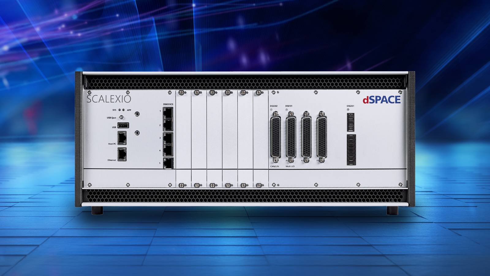
India’s mobility industry is large and varied. Indian automakers sold a record 28.3 million vehicles domestically in FY26, up 10.4%, and exported 6.6 million, up 24%, according to SIAM. Automotive and nonautomotive OEMs alike must simulate many vehicle types, operating conditions and scenarios. Nasscom estimates India’s engineering R&D services revenue at $63 billion in FY26 and projects it will exceed $100 billion by 2030.
That demand drove one of the conference’s clearest themes: a concerted push for test solutions designed and engineered locally for India, shaped by Indian programmes and delivered with local partners.
Customer Perspectives: Validation Challenges Across Industries- Customers described using dSPACE to manage large numbers of vehicle variants in a virtual environment and accelerate testing.
- Speakers showed how emerging aerospace companies can test flight-control laws safely and precisely before flight tests.
- Multiple speakers raised the testing challenges of software-defined vehicles, including continuous regression and reproducible, scalable end-to-end validation, and how dSPACE addresses them.
The technologies unveiled for the Indian market address the needs customers described:
- Neural Net Coder converts trained neural networks into deterministic, standards-compliant C code for safety-critical, resource-constrained embedded systems. It includes post-training optimisation, built-in verification and early estimates of runtime and memory use.
- dissecto HydraProbe is an ECU security test tool that adds controlled penetration testing to existing HIL systems, speeding up cybersecurity testing and giving teams results they can rely on as evidence throughout the validation lifecycle.
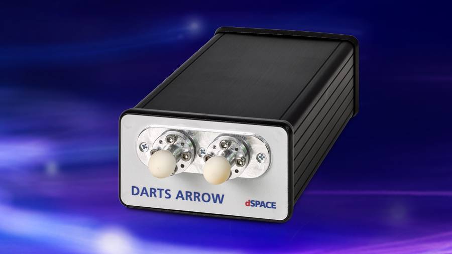
- DARTS ARROW is a compact radar target simulator for functional, end-of-line and periodic inspection testing across 76–81 GHz, with ranges up to 500 metres and simulated speeds up to ±700 km/h.
- SCALEXIO Essential is an entry-level, component-level HIL platform for quick validation of edge ECUs, supporting automotive Ethernet, CAN, LIN and analogue, digital and resistance I/O.
AI is moving into embedded mobility systems, and the harder task is no longer building a model but proving how it behaves on an ECU inside a larger physical system. Neural Net Coder covers the path from trained network to verified embedded code. The wider dSPACE environment, from SIL to HIL, tests that behaviour before deployment.
“India’s engineers are building for domestic and global markets at a scale few countries match, and they are being asked to prove software works before there is a vehicle to prove it on. This conference showed Indian teams combining partner technologies into turnkey workflows, and it showed the demand for test solutions designed for Indian programmes. The four technologies we introduced, including Neural Net Coder for AI in the ECU, are our answer to that demand,” said Andreas Gau, CEO, dSPACE India Solutions Pvt. Ltd.
The question is no longer whether a system can be tested, but how early, how comprehensively and how repeatedly it can be validated before it reaches the road, the factory floor or the flight line.
The post dSPACE India 2026 Conference Highlights AI, ECU Cybersecurity and HIL Testing appeared first on ELE Times.
University of Illinois at Urbana-Champaign (UIUC) has achieved a record modulation bandwidth of 2.75GHz in a gallium nitride (GaN) blue micro-LED (Abdelghany Abouelnagga et a
Palomino gains first commercial purchase order from strategic hyperscaler customer
DRDO Successfully Tests Indigenous High-Altitude Surveillance Platform
The Defence Research and Development Organisation (DRDO) has completed a flight trial of a high-endurance Indigenously Developed High-Altitude Platform (HAPS). As stated by the Ministry of Defence, the stratospheric platform ascended to an altitude of 21 kilometres above mean sea level and stayed at 20 kilometres for over 30 minutes before descending and being recovered successfully.
As it was being tested, the vehicle broadcast live video and vehicle-status information to a ground control station. It had onboard an inertial measurement unit, a GPS receiver, cameras, and an altitude control. The system is under development by DRDO’s Aerial Delivery Research and Development Establishment (ADRDE) at Agra. The trial was carried out in conjunction with the Indian Air Force along with other Aviation and certification authorities.
Elevated platforms could enable long-term surveillance or other applications requiring continuous monitoring in the stratosphere. The test also provided performance data for technology development but is not a systems demonstration.
The post DRDO Successfully Tests Indigenous High-Altitude Surveillance Platform appeared first on ELE Times.
Pages