


Збирач потоків
Fetal dopplers: Physics, anatomy, and audio signatures of prenatal listening

To the untrained ear, it’s a mesmerizing rhythm; to an engineer, it’s a masterclass in continuous wave (CW) ultrasound. Capturing a fetal heartbeat means navigating a complex landscape of acoustic impedance, shifting frequencies, and maternal anatomy.
There’s a moment in pregnancy that feels almost magical—the first time you hear the rhythmic thump of your baby’s heartbeat. Traditionally, this experience belonged to the OB-GYN’s office, where trained professionals used specialized equipment to reassure expectant parents. But in recent years, that sound has traveled beyond the clinic walls, finding its way into living rooms through a small, handheld device: the fetal doppler.
At first glance, it seems like a miracle of accessibility—technology that lets families connect with their unborn child anytime they wish. Yet, as with most medical tools, the story is more nuanced. A fetal doppler is not a toy; it’s a diagnostic instrument repurposed for consumer use. Understanding what it is, how it works, and the realistic pros and cons of at-home listening is essential.
In this post, we’ll explore the science, the emotional appeal, and the safety guidelines that should shape responsible use.
Fetal doppler basics: Sound over sight
At its core, a fetal doppler is a handheld ultrasound device designed to pick up the sound of a baby’s heartbeat. It relies on the Doppler Effect—a principle you’ve likely experienced when a siren changes pitch as it speeds past. The device sends high‑frequency sound waves into the abdomen; when those waves bounce off moving structures like a tiny, pumping heart, they return at a slightly different frequency. The doppler translates those shifts into the familiar “whoosh‑whoosh” sound of a heartbeat.
To make this possible, users apply ultrasound gel to the probe before placing it on the skin. The gel isn’t just for comfort—it eliminates air pockets between the device and the body, allowing sound waves to travel smoothly. Without it, the signal would scatter and fade.
It’s important to note that a fetal doppler is not the same as a full ultrasound scan. While dopplers capture sound, clinical ultrasounds create detailed images of the fetus and surrounding structures. In other words, the doppler lets you listen, but it doesn’t let you see. This distinction underscores both the accessibility and the limitations of at‑home devices.

Figure 1 A pocket fetal doppler with a 3-MHz probe captures low-amplitude Doppler-shifted signals from the fetal heart. Source: KernMed
At‑home vs. medical‑grade dopplers
Not all dopplers are created equal. The handheld device you can order online for around $40 is a far cry from the equipment used in a doctor’s office or by a midwife. Medical‑grade dopplers are built with higher sensitivity, meaning they can detect faint signals from a tiny fetal heart earlier and more reliably.
They also feature advanced noise‑filtering circuits that reduce interference from maternal blood flow or background movement. Just as importantly, these professional devices are regularly calibrated to ensure accuracy, a step that consumer units rarely undergo.
By contrast, at‑home dopplers are simplified, mass‑market versions. They may pick up a heartbeat, but they’re more prone to false positives (like mistaking maternal pulse for fetal heart sounds) or false negatives if the probe isn’t positioned correctly. While they offer emotional reassurance, they lack the precision and reliability of clinical tools. Understanding this gap is key to using them responsibly.
When can you hear the heartbeat and how to use it safely
For most families, the first audible heartbeat comes between weeks 12–16, when at‑home dopplers begin to consistently pick up the sound. Earlier detection—around weeks 8–12—is possible in a doctor’s office with medical‑grade equipment, but it’s often unreliable at home.
Even within the “sweet spot,” factors like an anterior placenta, the baby’s position, or simply being at the early edge of gestation can make the heartbeat harder to find. Knowing this helps prevent unnecessary panic if silence greets the probe.
Safe use starts with preparation: a full bladder (which helps lift the uterus), lying flat, and applying plenty of gel to eliminate air gaps. Begin the search low, near the pubic bone, and rock the probe slowly rather than sliding it quickly. When successful, you’ll hear the baby’s heart racing like a galloping horse or rapid train—usually 110–160 beats per minute.
By contrast, maternal sounds include the slower thump of the mother’s pulse or the swooshing rhythm of placental blood flow. Recognizing these differences is key to avoiding confusion and using the device responsibly.
Pros and cons plus expert guidelines
At‑home dopplers can feel like a lifeline, offering families a way to connect with their baby between appointments. The pros are easy to see: they provide instant connection, letting partners and siblings share in the experience, and they can ease anxiety for parents who’ve faced pregnancy loss.
But the cons are just as real. A heartbeat doesn’t guarantee that everything is fine, and relying on that sound alone can delay urgent medical care if fetal movement decreases. On the flip side, not finding the heartbeat—often due to baby’s position, placenta placement, or simple user error—can trigger unnecessary panic.
Medical experts urge caution. The FDA recommends that fetal dopplers be used only by or under the supervision of healthcare professionals. While ultrasound waves themselves are generally safe, prolonged or improper use can theoretically cause slight tissue heating. The greater risk lies in misinterpretation: families may either be falsely reassured or unduly alarmed. In short, these devices can be meaningful tools for bonding, but they should never replace professional guidance.
The physics of doppler ultrasound
Now let’s step beyond the emotional resonance and into the engineering core of how fetal dopplers actually work.
At the foundation is the Doppler Effect—the same principle that makes a passing siren change pitch. A fetal doppler’s transducer emits continuous, high‑frequency ultrasound waves in the 2–3 MHz range. When these waves encounter moving targets—like red blood cells coursing through the fetal heart or umbilical cord—the reflected frequency shifts slightly. The device captures this frequency delta and translates it into sound, producing the rapid “whoosh‑whoosh” heartbeat that parents recognize.
While most handheld fetal dopplers operate between 2 MHz and 3 MHz, the choice of frequency carries practical trade‑offs. A 2-MHz probe penetrates deeper, making it more effective for women with higher BMI or later gestational stages. A 3-MHz probe offers crisper resolution at shallower depths, often preferred in early pregnancy when the fetal heart is closer to the abdominal surface. Engineers balance these parameters to optimize sensitivity without sacrificing safety, illustrating how MHz selection is more than a specification—it’s a design decision rooted in anatomy and physics.
Most handheld dopplers rely on CW ultrasound. One crystal transmits continuously while another receives, creating a steady stream of reflections that can be converted into audio. In contrast, diagnostic imaging systems use pulsed wave (PW) ultrasound, which alternates between sending and receiving. PW enables depth resolution and visual mapping (seen in B‑mode scans), while CW is limited to audio feedback without imaging.

Figure 2 Compact fetal doppler monitors fetal heart rates during routine examinations for obstetricians, midwives, and expectant mothers. Source: pregnancy & baby.ie
Finally, the role of acoustic impedance is critical. Air is a poor conductor of high‑frequency sound, scattering waves before they reach tissue. That’s why ultrasound gel is indispensable: it eliminates air pockets, minimizes impedance mismatches, and ensures efficient coupling between probe and skin. Without gel, the doppler’s signal would degrade, making detection unreliable.
In essence, fetal dopplers are elegant demonstrations of applied physics—transforming MHz‑range ultrasound reflections into audible signatures of life, while highlighting the trade‑offs between sound and image that engineers must balance.
Gestational timeline and anatomical confounders
The physics of doppler ultrasound only tells half the story. The other half lies in how pregnancy anatomy changes over time, shaping when and how a fetal heartbeat can be detected.
In the first trimester (8–11 weeks), the uterus remains tucked deep within the true bony pelvis. This positioning makes acoustic detection extremely difficult, even with medical‑grade equipment. Around weeks 12–14, the uterus ascends into the abdominal cavity. Once it rises above the pelvic brim, the fetal heart becomes more accessible to a transducer probe, marking the point when at‑home dopplers begin to consistently pick up sound.
Here, probe frequency plays a role. A 3-MHz probe is often favored in early pregnancy, when the fetal heart lies closer to the abdominal surface, offering sharper resolution. By contrast, a 2-MHz probe penetrates deeper, making it more effective later in gestation or in cases where maternal tissue density is higher. This frequency choice interacts directly with anatomy, underscoring how engineering design must adapt to biological variation.
Even within this window, anatomical confounders can complicate detection. An anterior placenta—positioned at the front of the uterine wall—acts like an acoustic muffler, dampening returning signals. Maternal tissue density or higher BMI increases the distance ultrasound waves must travel, attenuating their strength. And a retroverted uterus, tilted backward rather than forward, alters the probe’s angle of approach, requiring more patience and precision.
Understanding these variables is crucial. They explain why a heartbeat may not be immediately audible, and they help reduce unnecessary panic when silence meets the probe. For engineers, these confounders highlight the importance of sensitivity, calibration, and acoustic design in consumer doppler devices.
Acoustic differentiation: The audio signatures
One of the greatest challenges in at‑home doppler use is not the physics of ultrasound, but the interpretation of what you hear. Misidentifying maternal blood flow as the baby’s heartbeat—or vice versa—can lead to false reassurance or unnecessary panic. Engineers and clinicians alike emphasize the importance of recognizing distinct audio signatures.
Fetal cardiac activity typically ranges between 110–160 beats per minute (BPM). The sound is rapid, crisp, and rhythmic, often likened to a galloping horse or a distant locomotive. Its pace and clarity distinguish it from slower maternal rhythms.
By contrast, the placental souffle is the sound of maternal blood rushing through uterine arteries. It matches the mother’s pulse rate—usually 60–100 BPM—and presents as a soft, low‑pitched, synchronous “swishing” or “swooshing.” This can easily be mistaken for fetal activity if the listener isn’t trained to note the slower cadence.
A third signature comes from umbilical cord flow. Blood traveling through the umbilical arteries matches the fetal heart rate but produces a sharper, mechanical “whistling” or “whooshing” rather than a distinct cardiac thump. It’s rhythmic and fast, but its tonal quality differs from the gallop of the heart itself.
For engineers, these distinctions highlight the need for filtering algorithms and signal processing that can help separate overlapping sounds. For families, they underscore why professional guidance matters: the heartbeat is more than just a sound—it’s a signal embedded in a complex acoustic environment.
Regulatory frameworks and the ALARA principle
Beyond physics and anatomy, fetal dopplers exist within a regulatory framework designed to protect users. The FDA has long emphasized that these devices should be used only by or under the supervision of healthcare professionals. Their concern is less about the ultrasound waves themselves—which are generally safe at diagnostic levels—and more about the risks of misinterpretation and delayed medical care.
For engineers, the guiding ethic is the ALARA principle: As Low As Reasonably Achievable. This concept, borrowed from radiation safety, applies equally to ultrasound. It means designing devices and usage protocols that minimize exposure while still achieving reliable detection. In practice, ALARA drives decisions about output power, duty cycles, and probe design. It also informs recommendations for short listening sessions rather than prolonged scanning.
By embedding ALARA into design philosophy, manufacturers balance accessibility with responsibility. The principle reminds us that even safe technologies demand respect: every extra milliwatt of acoustic energy, every unnecessary minute of scanning, is exposure that can—and should—be reduced. For clinicians, ALARA is a usage guideline; for engineers, it’s a design imperative. Together, they ensure that fetal dopplers remain tools of connection and reassurance without compromising safety.
Engineering the handheld doppler
From regulatory guardrails to circuit realities, the handheld doppler’s design chain shows how safety principles translate into hardware decisions.
Behind the familiar “whoosh-whoosh” lies a carefully tuned hardware chain. Designing a handheld fetal doppler means building an analog front end (AFE) optimized for continuous-wave architectures in the 2–3 MHz band. A 3-MHz probe enhances sensitivity for shallow signals in early gestation, while 2 MHz penetrates deeper for higher-BMI patients.

Figure 3 A waterproof 3-MHz fetal probe supports early pregnancy monitoring. Source: Newman Medical
Most handheld probes use a dual-element piezoelectric transducer to isolate the signal paths. On the transmit side, high-frequency driver circuits actuate the dedicated transmit crystal with high efficiency. On the receiver side, a dedicated low-noise amplifier (LNA) connected to the receive crystal pairs with an in-phase/quadrature (I/Q) demodulator to extract microvolt-level return voltages from abdominal tissue.
Once reflections are demodulated into the baseband audio spectrum (< 3 kHz), a low-power microcontroller or DSP running real-time autocorrelation filters out maternal vascular artifacts to calculate fetal heart rate. Safety remains the hard boundary: strict isolation barriers and capped driver thermal limits ensure acoustic intensity stays below 20 mW/cm² to align with ALARA principles.
Wrap‑up: Fundamentals in action
Fetal dopplers are more than sentimental gadgets. They are living demonstrations of applied physics, anatomy, and acoustic engineering. From MHz‑range ultrasound reflections to uterine ascent and placental positioning, every heartbeat heard at home is shaped by a complex interplay of science and structure.
The audio signatures—galloping fetal rhythms, placental swooshes, and umbilical whistles—remind us that listening is not the same as diagnosing. And the regulatory guardrails, anchored in the ALARA principle, ensure that connection never comes at the cost of safety.
For engineers, this is a case study in design trade‑offs: CW simplicity versus PW precision, consumer accessibility versus clinical calibration. For families, it’s a reminder that reassurance must always be paired with professional guidance.
Well, whether you are a parent marveling at the sound of life or an engineer refining the next generation of devices, carry forward the fundamentals. Respect the physics, honour the anatomy, and design—or use—technology with safety at its core. That is how prenatal listening becomes not just a moment of wonder, but a responsible practice rooted in science.
Every heartbeat heard is physics in practice—a reminder that fundamentals aren’t just theory, they’re life itself.
 T. K. Hareendran is a self-taught electronics enthusiast with a strong passion for innovative circuit design and hands-on technology. He develops both experimental and practical electronic projects, documenting and sharing his work to support fellow tinkerers and learners. Beyond the workbench, he dedicates time to technical writing and hardware evaluations to contribute meaningfully to the maker community.
Related Content
- Electronics For Medical Devices
- Developing GUIs for medical equipment
- Addressing Challenges of Medical Electronics
- Streamlining the design of portable medical electronics
- Adopting An SOC-based Approach to Designing Handheld Medical Devices
The post Fetal dopplers: Physics, anatomy, and audio signatures of prenatal listening appeared first on EDN.
Disassembling a low-tech liquid-leak detector

 What good is a non-networked water sensor? Still pretty good, as long as its existence, and specifically its embedded battery’s inevitable impermanence, are things you remember.
Back in March, I detailed the initial setup and ongoing usage impressions for a wireless sensing setup for my sorta-“smart” home, comprising TP-Link’s Tapo H100 smart hub.

Tapo T315 hygrometer (also available in a display-less option).

And Tapo T300 water (and other fluids) leak sensor.

The latter replaced a Gentronics model BWD-HWA leak sensor that had long sat at the base of our downstairs water heater, accompanied in the following photos by a 0.75′′/19.1 mm diameter U.S. penny for size comparison purposes.


As to why I made the hardware swap, here’s an excerpt from that initial March coverage, specifically discussing the original non-networked sensor.
Note, however, this bit in the operating instructions:
Replacing the battery: Replace the battery if the alarm has operated for an extended period of time, or if the battery expiration date is approaching. You may want to mark the battery expiration date on a piece of tape and attach it to the alarm when you install the battery.
Let’s be real. I know myself well enough to realize that once I set it, I’m going to forget it. I was admittedly surprised to learn, after replacing it (more accurately, moving it; it now sits below the whole-house water filter enclosure in a different room) that unlike my carbon monoxide detectors at their end-of-life dates, it didn’t at least chirp when its battery was getting low. That said, we’d only hear the sound if we were there at the time, and assuming it was loud enough to capture our attention. And further to that point, more generally, if we were away when a leak started, we’d be blissfully ignorant of what was going on…at least at first, until we returned home, that is.
As mentioned above, I originally just moved the original device elsewhere, replacing it at the water heater with the Tapo T300. That said, I eventually replaced the original in its new location with a Tapo T300, too, since the whole-house water filter is in a storage area with a normally closed, sound-muting door, and since the Tapo T300 successor is inexpensive (sub-$20).
The leak detector that time forgotEarlier this year, we got the upstairs hardwood floor resurfaced, and in preparation I rolled forward the kitchen refrigerator. Imagine my surprise to find another Gentronics BWD-HWA “Watchdog” Water Alarm behind it! The plumber had done a flurry of initial work when we moved into the residence, also including hooking up the water line to the new refrigerator for icemaker-feeding purposes, and apparently (and wisely) put a leak sensor there, too. While I could claim that I’d not been aware of its presence until now, more likely is that he’d told me about it and I’d promptly then forgotten not only about the need to periodically change its batteries but more broadly about its very existence.
Unsurprisingly, as exemplified by the barely audible “bark” (normally, quoting from the product page on the company website, a “piercing, 110 dB alarm”) when I used a moistened finger to span the “Watchdog’s” under-side electrical contacts, its 9V cell was nearly dead.

I promptly ordered a third Tapo T300 to succeed it. And since I now had two legacy leak sensors on my hands, I of course then decided to take one of them apart. Here’s where the now-drained battery used to be, behind a slide-away cover.

And here was a slick-feature surprise, at least to me. The panel containing the electrical contacts was removable, leading to its potential relocation up to 6 feet away from the base unit.

Had I seen the product web page in advance of the teardown, I might have realized this earlier (in my slight defense, I don’t remember getting any instructions; then again, I don’t remember getting the device itself, either, so…).

That said, I’m not sure what the manufacturer means on that same web page by this phrase (bolded emphasis is mine).
The alarm includes 6 feet of wire, which can be extended up to 100 feet, allowing the sensor to be used in hard-to-reach places.
Span extension mention = dissection invitation?I don’t see any way to detach the wire harness from the contacts ends for length-augmentation purposes. Surely, they don’t recommend taking the base unit apart, do they?

Just in case they do, though, I’m taking it as an implied disassembly solicitation (or at least sanction). The three back panel screws you may have noticed in an earlier photo are first to go.


With them out of the picture, the back panel comes right off.

Let’s focus on the “meat” of the hardware.

The three clips that hold the PCB in place detach straightaway.

Flip the PCB over, and its frontside comes into clear view.

Maybe I’m just being dense, but I still don’t see how to extend the wire harness beyond its 6’ default span in a consumer masses-friendly fashion.

I’m sure you’ve already noticed the alarm buzzer dominating the landscape. Aside from that, a discrete transistor (see the above image) and a smattering of passives, the only other notable thing to “write home about” is this IC, a Texas Instruments CD4069UB hex inverter.

And that’s as far as I’m going to go today. Even though these legacy leak sensors aren’t particularly “smart”, they’re still perfectly usable. As such, they’re destined for donation, to serve someone else far into the future. I’ll close with my usual invitation for reader observations in the comments!
—Brian Dipert is the associate editor, as well as a contributing editor, at EDN.
Related Content
- The Tapo Hub: TP-Link joins the low-bandwidth, long-range RF club
- Smart hygrometers: Still largely useful even without integrated visual monitors
- TP-Link’s Tapo H100: Smart sensing unencumbered
- TP-Link’s Tapo T300 sensor detects water and other liquid-leak dangers
- Disarming a carbon monoxide detector
The post Disassembling a low-tech liquid-leak detector appeared first on EDN.
Centralised Computing Architectures Are Replacing Traditional ECU-Based Designs: Robert Schweiger, Cadence
The mobility landscape across the globe is undergoing a paradigm shift towards connected technology, AI-enabled architecture, and acute software-reliance. Robert Schweiger, Sales Development Group Director, Cadence, in an exclusive interaction with Anwesh Koley of ELE Times, explained the myriad possibilities and challenges that the future of transportation holds and how Cadence is poised to address industry imperatives.
ELE Times: How is Cadence poised to make fully autonomous vehicles a reality today?
Robert Schweiger: Autonomous vehicles require much more than AI software. They need a complete ecosystem spanning sensors, high-performance computing, semiconductor design, software development, system verification, and safety validation. Cadence is uniquely positioned because we provide solutions across the entire stack, from silicon design and automotive IP to virtual platforms, software development, and Multiphysics system analysis.
Modern autonomous vehicles rely on cameras, radar, lidar, sensor fusion, AI accelerators, and centralised compute architectures. Cadence enables the development of highly complex SoCs by providing a fully customisable chiplet-based reference platform that helps customers to address challenges in functional safety, security, power efficiency, and early software validation.
ELE Times: Brief us about Cadence’s AI-driven DSPs and agentic design tools and how they enable engineers to handle complex neural workloads.
RS: Automotive AI workloads are growing exponentially, driven by perception, sensor fusion, driver monitoring, voice assistants, and automated driving functions. Cadence Tensilica DSPs and AI IP processor platform are designed specifically to process these workloads efficiently at the edge. Our Neo NPUs, and NeuroEdge AI Co-processor deliver scalable performance, from embedded sensing applications to high-performance autonomous driving platforms.
What differentiates Cadence is the combination of configurable DSP architectures, AI acceleration, and software development environments that allow customers to optimise performance, power, and latency for specific automotive workloads. Recent automotive audio and AI implementations also demonstrate how Tensilica architectures can accelerate neural-network processing directly on DSP platforms.
NeuroWeave is our unified AI Compiler Toolchain for all the IPs running AI. It enables customers to train any AI model in various open-source frameworks and targets any combination of processors, DSPs, and AI accelerators. This will help with faster model deployment and a better time to market.
ELE Times: Features like personalised audio zones, vital signs monitoring, and child presence detection are becoming standard. How does Cadence intend to address these consumer-facing demands through their offerings?
RS: The vehicle cabin is rapidly becoming an intelligent sensing environment. Consumers increasingly expect personalised experiences while regulators demand higher safety standards.
Cadence addresses these requirements through our Tensilica DSP portfolio, which enables advanced audio processing, voice recognition, occupant monitoring, radar processing, and AI-based sensing applications. Our solutions support applications such as personalised sound zones, active noise cancellation, immersive audio, voice assistants, vital-sign monitoring, driver monitoring, and child presence detection.
With Euro NCAP introducing stronger requirements around occupant monitoring and child presence detection, our DSP-based radar sensing solutions help OEMs and semiconductor providers deploy these capabilities efficiently while maintaining low power consumption and real-time performance.
ELE Times: The automotive industry is moving rapidly from domain-based architectures to SDVs and zonal E/E architectures. How is Cadence enabling technology proliferation in this domain?
RS: The shift to Software-Defined Vehicles is fundamentally changing vehicle electronics. Instead of more than a hundred distributed ECUs, OEMs are already transitioning to centralised computing platforms connected through zonal architectures. Cadence enables this transition through semiconductor IP, chiplet technologies, automotive networking solutions, virtual platforms, software development environments, and system-level design methodologies.
Zonal architectures require powerful centralised SoCs, high-bandwidth automotive Ethernet networks, robust safety and cybersecurity systems, and scalable software frameworks. Cadence provides a customisable chiplet-based reference platform that addresses all these areas. This platform includes a scalable architecture consisting of a base system chiplet that supports flexible configuration, a configurable AI accelerator, support for a CPU chiplet, and an optional domain-specific chiplet.
All chiplets communicate via a UCIe standards-based interface, enabling interoperability and connectivity with other chiplets. Our customers can design, verify, and optimise the complete system, from chip to package, board, and vehicle-level integration, allowing them to accelerate the adoption of zonal architectures and SDVs.
ELE Times: For SDVs, how do you bridge the gap between physical electromechanical automotive systems and software validation?
RS: One of the biggest challenges in SDVs is validating software against physical vehicle behaviour long before hardware becomes available. Cadence addresses this challenge through virtual prototyping, system simulation, and digital twin technologies. We enable software teams to develop and validate applications using highly accurate virtual representations of hardware and physical environments.
At the same time, our Multiphysics simulation portfolio allows engineers to model thermal, mechanical, multibody dynamics, electromagnetic, and fluid dynamics effects. With Hexagon MSC, one of our latest acquisitions, we can now connect software validation to physics-based system models, helping customers detect issues earlier, reduce physical prototyping costs, and significantly accelerate vehicle development schedules.
ELE Times: With automotive electronics shifting rapidly toward rigorous functional safety certifications and upcoming Euro NCAP requirements for in-cabin sensing, how is Cadence helping silicon vendors and Tier-1 suppliers accelerate market compliance?
RS: Functional safety has become a fundamental requirement for all automotive electronics. Cadence offers one of the industry’s most comprehensive automotive safety portfolios, covering safety-aware design flows, verification methodologies, FMEDA-driven design, safety analysis, and ISO 26262 compliance up to ASIL-D.
For in-cabin sensing, we leverage our ASIL-certified Tensilica processors for radar and AI-based solutions to enable vital-sign monitoring, occupancy detection, and child presence detection. These technologies help OEMs address emerging Euro NCAP requirements while maintaining scalability and cost efficiency. Our goal is to help customers achieve compliance earlier, reduce certification effort, and shorten time-to-market without compromising safety.
ELE Times: Please elaborate on the criticality of power electronics in the e-mobility sector. What are the initiatives from Cadence towards this end?
RS: Power electronics are the foundation of electrified mobility. They directly impact vehicle efficiency, driving range, charging performance, thermal behaviour, and overall reliability. As the industry transitions to silicon carbide (SiC) and gallium nitride (GaN) technologies, engineers face increasing challenges related to thermal management, power integrity, EMI, packaging, and reliability.
Cadence addresses these challenges through an integrated power-module design flow that combines circuit simulation, PCB design, packaging, thermal and warpage analysis, and system-level optimisation. Our Multiphysics approach helps designers optimise battery-management systems, inverters, power modules, and charging systems while improving efficiency and reducing development risk.
ELE Times: Any existing or upcoming challenges that you foresee in technology adoption and implementation across the automotive space?
RS: The challenges are no longer isolated to hardware or software. They span the entire vehicle ecosystem.
Key challenges include:
- Managing the complexity of SDV software stacks
- Scaling AI and autonomous computing platforms
- Accelerating validation of AI-driven systems
- Managing the transition to chiplets and advanced semiconductor nodes
- Ensuring functional safety and cybersecurity
- Handling thermal and power-density issues in centralised compute architectures
- Reducing development cost and time-to-market while maintaining quality standards
The companies that successfully master end-to-end system-level co-design across hardware, software, and physics domains will have a significant competitive advantage.
ELE Times: How does Cadence envision the evolution of technology in the automotive industry and what are the breakthroughs to watch out for?
RS: We believe four major trends will shape the next decade of automotive innovation:
- Software-Defined Vehicles becoming the dominant vehicle architecture.
- AI-powered vehicles, where perception, planning, diagnostics, and personalisation are enabled by advanced AI.
- Centralised and zonal computing architectures replacing traditional ECU-based designs.
- Vertical integration of OEMs to better master hardware-software development and optimisation
Breakthroughs to watch include a fully digital engineering and virtual validation, leveraging agentic AI workflows, which will dramatically reduce development cycles and enable continuous innovation. Cadence is investing across all these domains to help the industry deliver safer, smarter, and more sustainable vehicles.
The post Centralised Computing Architectures Are Replacing Traditional ECU-Based Designs: Robert Schweiger, Cadence appeared first on ELE Times.
KryonOS: a JavaScript operating system for the ESP32
KryonOS turns an ESP32 from a device with fixed firmware into a reusable platform. The open source operating system by Haris16-code brings a desktop-style graphical interface and a JavaScript runtime to the ESP32 and ESP32-S3. You install it once and never reflash again: applications are written, installed and exchanged as on a small computer. The runtime is at version v2.0.0 with API Level 2, and apps have roughly 90 KB of usable RAM available.
At its heart is Duktape, an ECMAScript 5.1 JavaScript engine with some more recent features. Applications run inside that engine, so nothing needs to be recompiled. The system also offers a launcher, a file manager, an App Store and cloud services. Anyone who wants to get their hands on the code will find everything in the Haris16-code repository.
The multi-board HAL and supported displaysA multi-board HAL abstracts the hardware and holds together very different configurations. The list of supported boards includes:
- ESP32-S3 DevKitC-1, with 16MB of Flash and 8MB of Octal PSRAM
- ESP32 DevKit v1 with WROOM-32, 4MB of Flash
- M5Stack Cardputer v1.1, 8MB of Flash with dual OTA
- LilyGO T-HMI, 240×320 ST7789 display on 8-bit parallel
- ESP32-CYD-28, the Cheap Yellow Display
On the display side the HAL handles ILI9341 at 240×320 over SPI, ST7789V2 at 240×135 over SPI and XPT2046 touch. The Cardputer adds a physical 56-key matrix keyboard. There is also support for multi-bus SD cards and for parallel displays. Anyone who wants to start from a ready-made base will find in the catalogue a TFT display with resistive touch and SD slot, useful for building a complete panel without wiring the touch by hand.
 KryonOS running on an M5Stack Cardputer
The graphics use double buffering with mini-sprite support, so rendering produces no tearing or flicker. On top of that sits Kryon3D, the 3D engine that handles wireframes, shaded polygon meshes, camera, lights and fog. For the maths there is FastMath with a precomputed 360-degree LUT.
The JavaScript APIs give direct access to the hardware: GPIO, scanning and transfers on the I2C bus, high-frequency PWM tone generators, cryptographic hashing and hardware AES, battery monitoring via ADC. The filesystem is LittleFS. An application can therefore read a sensor, drive a speaker or write to memory without dropping down into C code.
Wireless OTA updates are anti-rollback and use two-level manifests, update.json. Flashing proceeds in 4KB chunks with MD5 integrity verification and automatic bootloader recovery. As a result, an interrupted update does not leave the board mute. For development, PlatformIO and esptool.py are used, with flashing at 921600 baud; alternatively there is the ESP Flash Download Tool.
Around the system, KryonCloud, the App Store cloud marketplace, Kryon.ai and System.ai, and the KryonBeam mesh messenger have grown up. Everything remains open source, so anyone who wants to study how a JavaScript runtime is built on a microcontroller starts from readable code.
Source: https://github.com/Haris16-code/KryonOS
Related productsThe post KryonOS: a JavaScript operating system for the ESP32 appeared first on Open Electronics.
dSPACE India 2026 Conference Highlights AI, ECU Cybersecurity and HIL Testing
More than 500 representatives from automotive and other industries, suppliers and global engineering companies attended the dSPACE User Conference India 2026 on 25 September at the Marriott Whitefield in Bengaluru. The conference focused on how companies can test and validate software before the physical hardware is built, helping identify potential issues early in the development process.
Held under the theme “Software-defined. Test-verified.”, the conference focused on how simulation and virtual testing can help engineers identify problems early in the development process. Murali Manohar of Ashok Leyland highlighted the importance of preventing defects before they reach the vehicle, rather than fixing them after they occur.
Partner Demonstrations Showed Turnkey, Deployable WorkflowsThe technology showcase centred on practical workflows built with dSPACE’s partner ecosystem, not standalone product demos:
- Generation of DO-178C certification artefacts with TargetLink and partner products
- V2X simulation to test vehicle behaviour for future autonomous and assisted-driving functions
- Cybersecurity penetration testing combined with simulation of real-world effects on the vehicle
- Generation of virtual ECUs with complete production software, with minimal downtime
The demos were integrated with the partner showcases, which showed customers that these solutions are deployable rather than conceptual. Together they showed Indian engineering teams combining technologies at pace and scale into turnkey solutions for customer programmes.
A Push for Locally Designed Test Solutions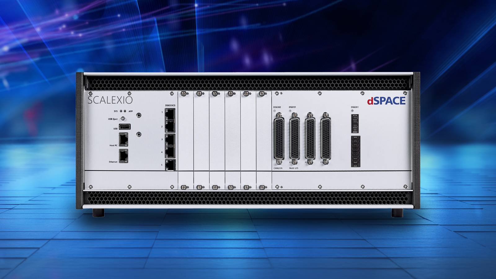
India’s mobility industry is large and varied. Indian automakers sold a record 28.3 million vehicles domestically in FY26, up 10.4%, and exported 6.6 million, up 24%, according to SIAM. Automotive and nonautomotive OEMs alike must simulate many vehicle types, operating conditions and scenarios. Nasscom estimates India’s engineering R&D services revenue at $63 billion in FY26 and projects it will exceed $100 billion by 2030.
That demand drove one of the conference’s clearest themes: a concerted push for test solutions designed and engineered locally for India, shaped by Indian programmes and delivered with local partners.
Customer Perspectives: Validation Challenges Across Industries- Customers described using dSPACE to manage large numbers of vehicle variants in a virtual environment and accelerate testing.
- Speakers showed how emerging aerospace companies can test flight-control laws safely and precisely before flight tests.
- Multiple speakers raised the testing challenges of software-defined vehicles, including continuous regression and reproducible, scalable end-to-end validation, and how dSPACE addresses them.
The technologies unveiled for the Indian market address the needs customers described:
- Neural Net Coder converts trained neural networks into deterministic, standards-compliant C code for safety-critical, resource-constrained embedded systems. It includes post-training optimisation, built-in verification and early estimates of runtime and memory use.
- dissecto HydraProbe is an ECU security test tool that adds controlled penetration testing to existing HIL systems, speeding up cybersecurity testing and giving teams results they can rely on as evidence throughout the validation lifecycle.
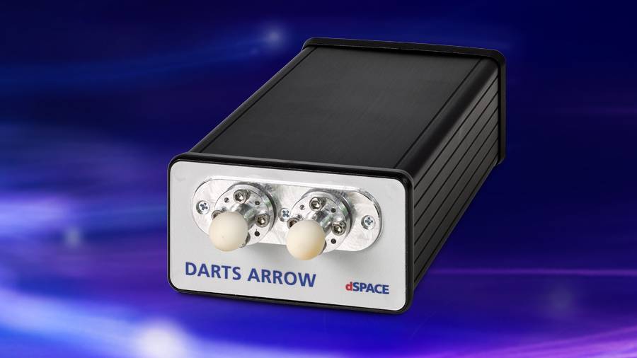
- DARTS ARROW is a compact radar target simulator for functional, end-of-line and periodic inspection testing across 76–81 GHz, with ranges up to 500 metres and simulated speeds up to ±700 km/h.
- SCALEXIO Essential is an entry-level, component-level HIL platform for quick validation of edge ECUs, supporting automotive Ethernet, CAN, LIN and analogue, digital and resistance I/O.
AI is moving into embedded mobility systems, and the harder task is no longer building a model but proving how it behaves on an ECU inside a larger physical system. Neural Net Coder covers the path from trained network to verified embedded code. The wider dSPACE environment, from SIL to HIL, tests that behaviour before deployment.
“India’s engineers are building for domestic and global markets at a scale few countries match, and they are being asked to prove software works before there is a vehicle to prove it on. This conference showed Indian teams combining partner technologies into turnkey workflows, and it showed the demand for test solutions designed for Indian programmes. The four technologies we introduced, including Neural Net Coder for AI in the ECU, are our answer to that demand,” said Andreas Gau, CEO, dSPACE India Solutions Pvt. Ltd.
The question is no longer whether a system can be tested, but how early, how comprehensively and how repeatedly it can be validated before it reaches the road, the factory floor or the flight line.
The post dSPACE India 2026 Conference Highlights AI, ECU Cybersecurity and HIL Testing appeared first on ELE Times.
University of Illinois at Urbana-Champaign (UIUC) has achieved a record modulation bandwidth of 2.75GHz in a gallium nitride (GaN) blue micro-LED (Abdelghany Abouelnagga et a
Palomino gains first commercial purchase order from strategic hyperscaler customer
DRDO Successfully Tests Indigenous High-Altitude Surveillance Platform
The Defence Research and Development Organisation (DRDO) has completed a flight trial of a high-endurance Indigenously Developed High-Altitude Platform (HAPS). As stated by the Ministry of Defence, the stratospheric platform ascended to an altitude of 21 kilometres above mean sea level and stayed at 20 kilometres for over 30 minutes before descending and being recovered successfully.
As it was being tested, the vehicle broadcast live video and vehicle-status information to a ground control station. It had onboard an inertial measurement unit, a GPS receiver, cameras, and an altitude control. The system is under development by DRDO’s Aerial Delivery Research and Development Establishment (ADRDE) at Agra. The trial was carried out in conjunction with the Indian Air Force along with other Aviation and certification authorities.
Elevated platforms could enable long-term surveillance or other applications requiring continuous monitoring in the stratosphere. The test also provided performance data for technology development but is not a systems demonstration.
The post DRDO Successfully Tests Indigenous High-Altitude Surveillance Platform appeared first on ELE Times.
BAE Systems Unveils High-Power Microwave and Advanced Artillery Defence Systems
BAE Systems has displayed two defence technology demos at AUSA 2026: The Multi-Domain Artillery Cannon System (MDACS) and a High-Power Microwave (HPM) system. They’re aimed at layered defence against unmanned aircraft and missile threats.
The MDACS is a kinetic system armed with precision-guided munitions (PGM) such as the Hypervelocity Projectile for an air defence role. In addition, the system is also intended to cater for a ground-target role with the company’s Scorpio XR munition.
HPM adopts a different approach that involves using directed electromagnetic energy to disable the electronics of an enemy drone. When employed against a drone, a regular missile has to be used for each attack, whereas the microwave system might neutralise several targets in one engagement (depending on its operational limits).
According to BAE: “The HPM architecture employs more than 99% commercial off-the-shelf elements.” The companies say they designed the technologies to work together with a fusion of physical and directed energy approaches to enhance counter-drone defence networks against large swarms.
The systems were pitched as capability demonstrators rather than validation of full-scale operational deployment.
The post BAE Systems Unveils High-Power Microwave and Advanced Artillery Defence Systems appeared first on ELE Times.
Raytheon Advances Coyote Interceptor to Counter Emerging Drone Threats
The upgraded Coyote Block 2C + RM designed by RTX passed three development tests since starting the programme, and has moved to testing from concept in around 15 months.
The modification expands on Coyote versions that have so far been able to shoot down hundreds of drones, according to the company. The new variant features new seekers and a warhead designed to counter a broader set of current and emerging drone threats, as well as a new tactical rocket motor to optimise launch and flight performance.
The latest series of tests involved integration with the counter-drone architecture and the first test firing of an interceptor with the tactical rocket motor. The goal is to enable faster rates of engagement and quicker follow-up shots.
The programme demonstrates the expanding need for counter-unmanned aerial systems (C-UAS) as armed forces attempt to defend sites and troops targeted by ever more effective drones. The tests are a milestone in the development process; they do not alone mean that the various features and applications planned have been fully qualified or deployed in operational service.
The post Raytheon Advances Coyote Interceptor to Counter Emerging Drone Threats appeared first on ELE Times.
Leonardo DRS Launches Digital Radar for Air and Missile Defence
Leonardo DRS has launched its cxMHR (C-Band Extended Multi-Mission Hemispheric Radar) and stated that the first units have entered production. The system was announced at the annual Association of the United States Army exhibition in Washington. D.C.
The system is based on a fully digital, software-defined C-band active electronically scanned array (AESA) radar. The four radar panels, identification-friend-or-foe (IFF) equipment, and command-and-control systems are incorporated within a containerised unit designed to be transported by land, air, or sea.
As per the manufacturer, the cxMHR gives 360-degree coverage in the form of a full hemispheric field of regard and can track multiple threats, including cruise missiles, tactical ballistic missiles, rockets and unmanned aircraft systems. Its artificial intelligence-powered tracking and classification is intended to enhance target recognition and offer swift updates on tracking.
The system is designed to operate as part of larger integrated air and missile defence (IAMD) networks, providing a mobile solution for military users to identify and track various types of aerial threats.
The post Leonardo DRS Launches Digital Radar for Air and Missile Defence appeared first on ELE Times.
Indian Army to Receive Rs 770 Crore Advanced Radar Systems
India’s Ministry of Defence has signed a contract worth around Rs 770 crore with Bharat Electronics Limited (BEL) to procure Improved Low-Level Weight Radars (LLLR-I) for the Indian Army. Revealed on 21 October 2026, the radar system can identify and track fighter-sized air targets, along with micro and mini-drones. The radar can also prioritise aerial threats, allowing for a quicker threat- and air-defence response.
The acquisition aims to strengthen the Army’s ability to counter emerging unmanned aerial system (UAS) threats, which have become an important concern in modern warfare. The agreement also advances India’s defence-indigenisation goals by facilitating the domestic defence industry and opening up opportunities for micro-, small, and medium-scale enterprises. The procurement is yet another initiative to enhance India’s layered air-defence architecture with indigenous sensor technology.
The post Indian Army to Receive Rs 770 Crore Advanced Radar Systems appeared first on ELE Times.
Vector and SCSK simplify embedded development on Renesas RL78/F2x
Vector and SCSK Corporation have developed a joint evaluation bundle to simplify the development of sensor and actuator applications based on Renesas RL78/F2x microcontrollers. By combining Vector’s MICROSAR IO with SCSK’s QINeS-Lite platform and drivers, the bundle offers a pre-integrated software base that reduces integration effort and speeds up configuration and evaluation. SCSK is a leading Japanese provider of IT services and automotive software solutions.
Joint evaluation bundle for embedded software developmentThe jointly developed evaluation bundle is aimed at developers who are evaluating or building embedded applications on resource-constrained microcontrollers. By combining Vector’s MICROSAR IO with SCSK’s QINeS-Lite platform and drivers for Renesas RL78/F2x microcontrollers, the solution provides a ready-to-use software base and supports initial evaluation activities while reducing configuration and integration effort. Customers can request the joint MICROSAR IO evaluation bundle for Renesas RL78/F2x from Vector via www.vector.com/pr-bundle-microsar-io.
A lightweight software base for sensor and actuator applicationsMICROSAR IO was developed specifically for sensor and actuator applications and provides a lightweight software platform for microcontrollers with limited hardware resources. The solution helps reduce software complexity, cut development effort and shorten time-to-market. QINeS-Lite is SCSK’s lightweight automotive software platform for small ECUs. It supports edge ECU applications that require high-speed communication, over-the-air software updates, cybersecurity and diagnostic capabilities. The drivers provided by SCSK are based on the open Chiisai specification and complete MICROSAR IO with the hardware abstraction layer needed for the Renesas RL78/F2x platform.
Reducing integration effort for Software-Defined Vehicle architecturesWith this joint offering, Vector and SCSK provide an accessible development base for sensor and actuator applications on Renesas RL78/F2x microcontrollers. The collaboration helps customers improve software reusability and prepare efficient edge ECU solutions for future Software-Defined Vehicle architectures. More information at: www.vector.com/microsar-io.
The post Vector and SCSK simplify embedded development on Renesas RL78/F2x appeared first on Open Electronics.
Got a toroidal transformer for my collection!
 | Salvaged from an old amplifier that my father brought for me from a junk shop [link] [comments] |
I built a sequencer!
 | https://www.youtube.com/watch?v=UJiyGaUV1Rs This is functionally a sequencer, but a dysfunctional midi controller as of now. There is still a lot of room for improvement, and will definitely not be my last rendition. I used an Arduino R3 Uno, 4 buttons, and joystick, the Arduino IDE program, and ton of github resources. I plan on upgrading to a teensy 4.1 eventually with an expanded patchbay to move beyond the prototype board. ...maybe throw some laser beams in there too. [link] [comments] |
Mouser Ships Nearly 70,000 YAGEO Group Products
Mouser Electronics, an authorised global distributor with the widest selection of semiconductors and electronic components, is shipping a broad range of new products and solutions from the YAGEO Group, a leading global manufacturer of passive components. With more than 300,000 parts available to order and almost 70,000 YAGEO Group products in stock — including YAGEO, KEMET and Pulse Electronics — Mouser offers a complete portfolio of the latest YAGEO Group products and solutions.
KO-CAP capacitorsYAGEO Group KO-CAP capacitors are tantalum capacitors with an organic polymer, designed for applications that demand hold-up protection and maximum circuit energy efficiency in small spaces. The conductive polymer cathode of these solid electrolytic capacitors delivers very low ESR and high capacitance retention at high frequencies. Unlike liquid electrolyte capacitors, KEMET polymer capacitors offer a very long operating life and high ripple current capability, making them ideal for solid-state drives (SSDs), enterprise storage, networking and servers.
SCFx and SCTx common mode inductorsThe YAGEO Group SCFx and SCTx high-performance common mode inductors offer a rated current of up to 22 A for the single-phase version and up to 110 A for the three-phase version. The SCFx series is built around a nanocrystalline core, while the SCTx series uses a proprietary Mn-Zn ferrite core. Thanks to their very high inductance and permeability, these inductors suit audio-video equipment, office automation equipment, industrial equipment, air conditioners, home appliances, digital devices and power supplies.
CE X5R multilayer capacitorsThe YAGEO Group CE X5R multilayer ceramic capacitors are Class 2 embedded capacitors designed for compact module assembly, with capacitance values from 10 nF to 220 nF. Their construction, a rectangular ceramic dielectric with interleaved metal electrodes, provides high capacitance per unit volume while reducing parasitic inductance. The capacitors support customisation of thickness and termination dimensions for embedding under ICs, ensuring excellent electrical bonding and advanced resonance.
HXE1 high-voltage isolation modulesThe YAGEO Group HXE1 10 kV high-voltage isolation modules are designed for 100Base-TX applications and are available in single-channel or single-port (dual-channel) versions. The HXE1 modules support IsoSPI for BMS solutions and 100Base-T1 for industrial STPE. These high-voltage isolation modules comply with the IEEE 802.3u 100Base-TX standard.
Content and resources for designersBesides offering a wide selection of YAGEO Group products, Mouser is proud to work with YAGEO Group to produce engaging content for design engineers and purchasing professionals, such as an automotive content stream and eBooks. In the eBook Powering the New Automotive Era with Smart Passive Solutions, industry experts explore how passive electronic components are evolving to meet the needs of increasingly electrified automotive systems.
To learn more about the YAGEO Group products available from Mouser, visit the site. For further Mouser news and the latest new product introductions, visit the site.
As an authorised global distributor, Mouser offers the widest selection of the latest semiconductors, electronic components and industrial automation products. Mouser customers can count on 100% certified, genuine and fully traceable products from each of its manufacturer partners. To accelerate customer designs, the Mouser website hosts an extensive library of technical resources, including a Technical Resource Centre, along with product datasheets, supplier-specific reference designs, application notes, technical design information, engineering tools and other useful information.
Engineers can stay up to date on exciting new products, technologies and applications through Mouser’s free electronic newsletter. Subscriptions to Mouser’s email news and references can be customised to the unique and changing design needs of customers and subscribers. No other distributor gives engineers this level of customisation and control over the information they receive. To learn about emerging technologies, product trends and more, you can sign up today.
The post Mouser Ships Nearly 70,000 YAGEO Group Products appeared first on Open Electronics.
An Open Source Tricorder with Thermal Imaging and Spectroscopy
Picture a portable box full of scientific sensors, designed to explore environments and make discoveries in the field. Dr. Peter Jansen’s open source tricorder does exactly that: it is a prototype built around a Clockwork Pi UConsole that integrates thermal imaging, visible spectroscopy, magnetic imaging, radiation spectroscopy and environmental sensors. All in a handheld format.
The UConsole uses a Raspberry Pi compute module, so it runs Linux and has about 4 GB of RAM. That lets it handle a user interface written in Python and analyse the data coming from the sensors. What’s more, the project is completely open: anyone who wants to study it or derive a personal version will find all the files available.
The tricorder’s sensors and their numbersThe heart of the device is its sensor suite. Each one covers a different measurement band, so the tricorder can observe the environment from several points of view at the same time.
- Waveshare Long-wave IR Camera: 80×62 pixel thermal imaging
- Waveshare IMX378 12MP: 12 megapixel visible camera
- Hamamatsu C12666MA: spectrometer with 256 spectral channels between 340 nm and 780 nm, effective resolution of about 15 nm
- SparkFun Magnetic Imaging Tile 8×8: 64 pixel magnetic camera, up to about 20 kHz
- Pomelo Spectroscopic Radiation Detector: radiation detection
- Sensirion SPS30: particulate matter measurement
The magnetic camera deserves a section of its own. Its 64 pixels may seem few, but the acquisition rate reaches about 20 kHz, that is 20,000 frames per second. So it can follow fast magnetic phenomena that a traditional camera would not see. The Hamamatsu spectrometer, on the other hand, covers the whole visible band with 256 channels and a spectral resolution of about 15 nm.
ESP32 firmware and JSONL packets to the UConsoleNot all the sensors speak the same language. Some connect directly to the UConsole over USB. The others are polled periodically by firmware on an ESP32, which collects the measurements and sends them to the UConsole over a USB-to-Serial connection. The data packets are in JSONL format, so the software on the UConsole can parse them easily.
The sensors are wired up in different ways. The Hamamatsu spectrometer, the magnetic imaging tile and the environmental sensors go through dedicated breakouts. The back plate hosts the environmental sensors with the Sparkfun mounting pattern, which measures about 25×25 mm, and the QWIIC hub. That way the wiring stays tidy and every sensor has its place.
For anyone who wants to rebuild the project, Dr. Peter Jansen’s code repository collects the ESP32 firmware, the Python interface, the EAGLE 9.6.2 project files with schematics and board, and the OpenSCAD models with the .scad sources and the exported STLs.
3D printing, M4 screws and press-fit insertsThe enclosure and the sensor mounts are 3D printed. The main body replaces the back of the UConsole and is fastened with four M4 screws at the corners. The press-fit inserts used are mainly M2.5, with some M2 and M3. So anyone who wants to replicate the assembly has to get hold of these inserts and the matching screws.
The cost of the components is not trivial. The UConsole, the CM4 compute module and the HackerGadgets expansion boards probably cost between 300 and 400 dollars. Adding the sensors and the build, the complete cyberdeck comes to around 1000 dollars. Even so, the project remains open and anyone who wants to can start from a reduced configuration and add the sensors later.
If you need a board for another computing project, the catalogue offers the Raspberry Pi 400 computer with Italian keyboard layout, which integrates a 4 GB Raspberry Pi 4 board. For more recent applications there is also the Raspberry Pi 5 with 2 GB of memory, with a quad-core Broadcom BCM2712 processor at 2.4 GHz.
Source: https://github.com/tricorderproject/cyberdeck
Related productsThe post An Open Source Tricorder with Thermal Imaging and Spectroscopy appeared first on Open Electronics.
Samtec backs the SGeT oHFM.c standard with high-performance interconnects
Samtec, Inc., a leader in connector services, announces a new product range designed for the SGeT oHFM.c standard. These connectors are based on Samtec’s proven AcceleRate® HD and AcceleRate® HP families, known for their high density and high performance.
What oHFM isoHFM , short for Open Harmonized FPGA Module, is the world’s first open modular standard for FPGAs. It tackles the common challenges of unique pinouts, custom form factors and proprietary thermal concepts in FPGA and SOM development by providing a unified, scalable architecture. Ready-made blocks and clear design rules cut engineering time for a faster time-to-market.
SOMs based on connectors defined by the oHFM.c standard are optimised for compact high-speed interfaces, mid-range and high-end FPGAs, and field upgrades using Samtec connectors with a 5 mm or 10 mm stack height.
Samtec’s oHFM.c connectors feature high-density channels on a 0.635 mm pitch with performance targets of 64 Gbps PAM4 or 112 Gbps PAM4. Within each connector, the narrow edges of the Edge Rate® contact system are aligned with the connector body to reduce broadside coupling and crosstalk, optimising signal integrity. The Edge Rate contact system also has a smooth, wide milled mating surface that reduces wear and increases durability for high-cycle applications. Samtec’s IPC Class 3 compliant solder column termination technique is used to secure the connectors to the printed circuit board. The solder column termination offers superior solder joint reliability and excellent insertion loss and return loss performance.
Designed to meet the evolving needs of FPGA-based computing platforms, Samtec interconnect solutions enable scalable, flexible and reliable system architectures for next-generation embedded and edge applications.
Ordering and more informationSamtec SGeT oHFM.c connectors are available from stock and can be ordered directly from Samtec or through authorised distributors. For more information on Samtec interconnect solutions for SGeT oHFM.c applications, visit samtec.com/oHFM.
The post Samtec backs the SGeT oHFM.c standard with high-performance interconnects appeared first on Open Electronics.
Some appreciation for TI's datasheets
 | Multiple examples (with scope readings!), formulas for everything you need, and everything laid out so nicely (even if they're a bit long sometimes)... I can't count how many times an exact scenario I encountered was directly described somewhere in the datasheet. Great stuff. [link] [comments] |
Сторінки