
Збирач потоків
New edge AI-enabled radar sensor and automotive audio processors from TI empower automakers to reimagine in-cabin experiences
Texas Instruments (TI) today introduced new integrated automotive chips to enable safer, more immersive driving experiences at any vehicle price point. TI’s AWRL6844 60GHz mmWave radar sensor supports occupancy monitoring for seat belt reminder systems, child presence detection and intrusion detection with a single chip running edge AI algorithms, enabling a safer driving environment. With TI’s next-generation audio DSP core, the AM275x-Q1 MCUs and AM62D-Q1 processors make premium audio features more affordable. Paired with TI’s latest analog products, including the TAS6754-Q1 Class-D audio amplifier, engineers can take advantage of a complete audio amplifier system offering. TI is showcasing these devices at the 2025 Consumer Electronics Show (CES), Jan. 7-10, in Las Vegas, Nevada.
“Today’s drivers expect any car – entry-level to luxury, combustion to electric – to have enhanced in-cabin experiences,” said Amichai Ron, senior vice president, TI Embedded Processing. “TI continues to provide innovative technologies to enable the future of the automotive driving experience. Our edge AI-enabled radar sensors allow automakers to make vehicles safer and more responsive to the driver, while our audio systems-on-chip elevate the drive through more immersive audio. Together they create a whole new level of in-cabin experiences.”
Edge AI-enabled, three-in-one radar sensor increases detection accuracyOriginal equipment manufacturers (OEMs) are gradually designing in more sensors to enhance the in-vehicle experience and meet evolving safety standards. TI’s edge AI-enabled AWRL6844 60GHz mmWave radar sensor enables engineers to incorporate three in-cabin sensing features to replace multiple sensor technologies, such as in-seat weight mats and ultrasonic sensors, lowering total implementation costs by an average of US$20 per vehicle.
The AWRL6844 integrates four transmitters and four receivers, enabling high-resolution sensing data at an optimized cost for OEMs. This data feeds into application-specific AI-driven algorithms on a customizable on-chip hardware accelerator and DSP, improving decision-making accuracy and reducing processing time. The edge intelligence capabilities of the AWRL6844 sensor that help improve the driving experience include these examples:
- While driving, it supports occupant detection and localization with 98% accuracy to enable seat belt reminders.
- After parking, it monitors for unattended children in the vehicle, using neural networks that detect micromovements in real time with over 90% classification accuracy. This direct sensing capability enables OEMs to meet 2025 European New Car Assessment Program (Euro NCAP) design requirements.
- When parked, it adapts to different environments through intelligent scanning, reducing false intrusion detection alerts caused by car shaking and external movement.
To learn more, read the technical article, “Reducing In-Cabin Sensing Complexity and Cost with a Single-Chip 60GHz mmWave Radar Sensor.”
Deliver premium automotive audio with TI’s complete audio portfolioAs driver expectations grow for elevated in-cabin experiences across vehicle models, OEMs aim to offer premium audio while minimizing design complexity and system cost. AM275x-Q1 MCUs and AM62D-Q1 processors reduce the number of components required for an automotive audio amplifier system by integrating TI’s vector-based C7x DSP core, Arm cores, memory, audio networking and a hardware security module into a single, functional safety-capable SoC. The C7x core, coupled with a matrix multiply accelerator, together form a neural processing unit that processes both traditional and edge AI-based audio algorithms. These automotive audio SoCs are scalable, allowing designers to meet memory and performance needs, from entry-level to high-end systems, with minimal redesign and investment.
TI’s next-generation C7x DSP core achieves more than four times the processing performance of other audio DSPs, allowing audio engineers to manage multiple features within a single core. AM275x-Q1 MCUs and AM62D-Q1 processors enable immersive audio inside the cabin with features such as spatial audio, active noise cancellation, sound synthesis and advanced vehicle networking, including Audio Video Bridging over Ethernet.
“Dolby’s longtime collaboration with Texas Instruments has enabled incredible audio experiences in the home, which we’re now bringing into the car,” said Andreas Ehret, senior director of Automotive Business at Dolby Laboratories. “With TI’s C7x DSP core, we can now deliver the latest Dolby Atmos capabilities more efficiently, including support for even smaller form factor audio systems so nearly all vehicles can have Dolby Atmos. Together, these products can help turn every car ride into an immersive entertainment experience.”
To further optimize their automotive audio designs, engineers can use TI’s TAS6754-Q1 audio amplifier with innovative 1L modulation technology to deliver class-leading audio performance and power consumption, with half the number of inductors compared to existing Class-D amplifiers. The TAS67xx-Q1 family of devices, which integrates real-time load diagnostics required by OEMs, helps engineers simplify designs, decrease costs, and increase efficiency without sacrificing audio quality.
The post New edge AI-enabled radar sensor and automotive audio processors from TI empower automakers to reimagine in-cabin experiences appeared first on ELE Times.
Wifi Controlled, LED Matrix via Pico W
 | The website used to control the LED Matrix Source code for the circuit board (via tscircuit) Server and MicroPython Source: https://github.com/tscircuit/led-matrix-server/tree/main [link] [comments] |
Wifi Controlled, LED Matrix via Pico W
The website used to control the LED Matrix
Source code for the circuit board (via tscircuit)
Server and MicroPython Source: https://github.com/tscircuit/led-matrix-server/tree/main
Board Source: https://tscircuit.com/seveibar/pico-w-3x5-led-matrix
[link] [comments]
Wifi Controlled, LED Matrix via Pico W, Only one GPIO pin required!
| | The website used to control the LED Matrix Source code for the circuit board (via tscircuit) Server and MicroPython Source: https://github.com/tscircuit/led-matrix-server/tree/main [link] [comments] |
CES 2025: Moving towards software-defined vehicles
 Major CES 2025 theme: SDVs
Software-defined vehicles (SDVs) are a big theme at CES this year, shifting vehicles from hardware-centric upgrades to over the air (OTA) software upgrades. In order to do this, vehicle subsystems must rely on a, more or less, generic processing platform that can perform a wide variety of functions to serve the various aspects of a car. As shown in Figure 1, TI’s approach to this is shifting from a “domain” architecture to a “zonal” one where ECUs that were once custom-tailored to specific domains (e.g., powertrain, ADAS, infotainment, body electronic and lighting, passive safety) are now more location, or zone-, -based to reduce weighty wire harnessing and improve processor speeds.

Figure 1 Traditional domain versus zone architecture. Source: Texas Instruments
TI’s radar sensor, audio processors, Class-D amplifierTI’s automotive innovations are currently focused in powertrain systems; ADAS; in-vehicle infotainment (IVI); and body electronics and lighting. The recent announcements fall into the ADAS with the AWRL6844 radar sensor as well as IVI with the AM275 and AM62D processors and the class-D audio amplifier.
ADAS: passenger safety solutionThe AWRL6844 radar sensor uses 60-GHz millimeter-wave (mm-wave) with a 4×4 antenna array and edge AI models running on an on-chip TI-specific accelerator and DSP to support several in-vehicle safety measures including occupancy monitoring for seat belt reminders, child presence detection, and intrusion (Figure 2). Presently, OEMs resort to a combination of in-seat weight sensors, two UWB sensors for front-row and back-row child presence detection, and an ultrasonic intrusion module for the same direct-sensing safety measures, directly tracking human activity such as respiration, heartbeat, movement, etc.). The technology is designed to assist OEMs in meeting evolving regulatory safety requirements such as the Euro new car assessment program (NCAP) advanced that offers rewards to manufacturers for implementing advanced safety technologies as a means to complement its established star rating system. Yariv Raveh, the vice president and business unit management of radar stated, “In 2025 the Euro NCAP requirement for child presence detection will only award points for a direct sensing system and in the near future, the in-cabin sensing system must accurately distinguish between a child and an adult in order to provide a good user experience.”

Figure 2 A block diagram of TI’s AWRL6844 radar sensor and the three vehicle modes that the sensor can assist with (seat belt reminder, child presence detection, and intrusion detection). Source: Texas Instruments
IVI: Premium audio solutionSome of the features of the new AM275x-Q1 and AM62D-Q1 processors are the integration of two vector-based C7x DSP cores, multiple Arm cores, on-chip memory, an NPU accelerator, and audio networking with Ethernet AVB. The differences between the processors is highlighted in Figure 3. “Tier 1 suppliers must elect the appropriate processing components to meet all of their customer needs across their fleets. So, our answer is to provide two different architectures to give engineers the flexibility to choose across the range of use cases, all using the same audio processing family where engineers can design standalone and integrated premium audio systems across a range of performance levels with minimal additional hardware and software investment,” said Sonia Ghelani, TI’s product line manager for signal processing MCUs. The company is actively working with customers to incorporate AI into the audio signal chain for unique solutions in applications such as active noise cancellation (ANC) and road noise cancellation (RNC).

Figure 3 The AM275x DDR-less MCU and AM62D DDR-based process for premium audio in IVI applications. Source: Texas Instruments
IVI: Class-D audio amplifierThe TAS6754-Q1 class-D amplifier (Figure 4) is meant to assist engineers with implementing TI’s “1L” modulation scheme, a technology that lowers the inductor count per audio channel to one (hence the phrase “1L”). Modern vehicles can embed well over 20 speakers and, in an effort to reduce size, weight, and cost, class-D amplifiers are being used for their higher power efficiency and lower thermal dissipation. However, these amplifiers generally require two LC filters per audio channel to attenuate high frequency noise. “1L maintains class-D performance while reducing component count and cost, allowing the premium audio system to grow in terms of speakers and mics,” added Sonia Ghelani.

Figure 4 Sample vehicle speaker and mic distribution as well as a sample block diagram of an audio signal chain including TI’s class-D amplifier. Source: Texas Instruments
Blurring the lines between IVI and ADASOne major discussion during the press briefing involved the industry trend of integrating ADAS and IVI functions on a single SoC. “So today we see that they’re in two separate boards, however, more and more we’re seeing that they end up being in the same board,” said Mark Ng, TI’s director of automotive systems. Sonia Ghelani added with an example of an overlap between ADAS and IVI functions, “these chimes and seat belt reminders are ADAS requirements that fall into the audio domain. As we move into a world of software-defined cars with more zonal architectures, you’ll continue to see an overlap between the two.” She continued, “For TI it’s important that we understand exactly what the customer is trying to build so that we don’t silo these systems in one bucket or another, but rather understand what problems the customer is trying to solve.”
Aalyia Shaukat, associate editor at EDN, has worked in the design publishing industry for six years. She holds a Bachelor’s degree in electrical engineering from Rochester Institute of Technology, and has published works in major EE journals as well as trade publications.
Related Content
- Power Tips #136: Design an active clamp circuit for rectifiers at a high switching frequency
- Collaboration drives innovation in software-defined vehicles
- AI algorithms on MCU demo progress in automated driving
The post CES 2025: Moving towards software-defined vehicles appeared first on EDN.
A two transistor sine wave oscillator
Figure 1 shows a variation on a sine wave oscillator, it uses just two transistors and a single variable resistor to set the frequency.
![]() Figure 1 Just a couple of components are needed for a simple tunable sine wave oscillator.
Figure 1 Just a couple of components are needed for a simple tunable sine wave oscillator.
Wow the engineering world with your unique design: Design Ideas Submission Guide
The section around Q1 is a multiple-feedback-bandpass-filter (MFBF). The usual embodiment of this type of filter is shown in Figure 2.
![]()
Figure 2 A standard implementation of a MFBF.
The formulas for these filter can be found in almost any textbook (where C = C1 = C2):
![]()
![]()
![]()
Please note that the center frequency, among others, is determined by the resistance of R3. The gain of the filter is determined by the ratio of R2/R1 in such a way that Av = -R2/(2*R1). Usually this filter is implemented around an operational amplifier, it can also be implemented around an inverting transistor amplifier. However, because of the limited open-loop gain of the latter, the gain will be lacking at the higher frequencies.
The section around Q2 is an inverting amplifier, with an unloaded gain set by R8/R7. D1 and D2 together with R8 form a clipper to make sure that the signal offered to the MFBF is of constant level.
At the center frequency of the filter, the phase-shift is 180°. Together with the 180° phase shift of Q2 there is a total 360° phase shift at this frequency.The loop gain is >1 due to the ample gain of Q2. Thus, Barkhausen’s criteria are met.
The relative soft clipping of D1 and D2 together with the filtering of Q1 limits the amount of harmonics in the output signal. The passive components around Q1 determine the center frequency.
With the current values, the frequency can be set between 498 Hz and 1230 Hz by changing R3 between 1k and 6k. At the same time the output amplitude changes from 1.28 Vpp to 0.68 Vpp. The output shows around ~1% distortion (Figure 3).
![]()
Figure 3 The scope image shows the oscillator output at circa 1 kHz.
A variation in the supply voltage from 9 V to 12 V causes a frequency variation of only 2 Hz and a variation of output amplitude from 0.80 Vpp to 0.86 Vpp.
Cor van Rij blew his first fuse at 10 under the close supervision of his father who promptly forbade him to ever work on the house mains again. He built his first regenerative receiver at the age of 12 and his boys bedroom was decorated with all sorts of antennas and a huge collection of disassembled radios took up every horizontal plane. He studied electronics and graduated cum laude. He worked as a data design engineer and engineering manager in the telecom industry. And is working for almost 20 years as a principal electrical design engineer, specializing in analog and RF electronics and embedded firmware. Every day is a new discovery!
Related Content
- Simple 5-component oscillator works below 0.8V
- Ultra-low distortion oscillator, part 1: how not to do it.
- Clapp oscillator
- Oscillators: How to generate a precise clock source
- Clapp versus Colpitts
The post A two transistor sine wave oscillator appeared first on EDN.
CES 2025’s sensor design highlights

Sensing solutions—a vital ingredient in automotive, consumer and industrial applications—are prominent features in the offerings displayed at CES 2025 held in Las Vegas, Nevada on from 7 to 10 January. That encompasses sensing solutions packed into system-on-chip (SoC) devices as well as hardware components meshed with sensor fusion algorithms.
But the most exciting foray in this year’s sensor parade at CES 2025 relates to how artificial intelligence (AI) content is incorporated into sensing designs.
Read the full story published at EDN’s sister publication, Planet Analog.
Related Content
- MEMS group targets IoT sensor design
- Key design considerations, future of IoT sensors
- A new era in electrochemical sensing technology
- High-Performance Design for Ultrasound Sensors
- Designer’s Guide to Industrial IoT Sensor Systems
The post CES 2025’s sensor design highlights appeared first on EDN.
Energy Meter Definition, Types, Working, Construction & Diagram
An energy meter is a device that measures the electrical energy consumption in homes, commercial establishments, or industrial settings. It records the total energy usage, usually in kilowatt-hours (kWh), which is then used to calculate electricity bills. Energy meters play a vital role in managing energy consumption, ensuring accurate billing, and supporting energy efficiency measures. They are an essential part of modern electrical systems and are commonly found in homes, offices, factories, and other establishments.
Types of Energy Meters
Energy meters are classified into several types based on their design, application, and method of measurement. Here are the main types:
- Electromechanical Energy Meters (Analog Meters): These meters are the traditional type and have been in use for many years. They operate using a mechanical movement, which is driven by the flow of current. The meter features a rotating disc that spins as a result of the current flowing through it. The movement of the disc turns the dials, indicating the amount of electrical energy consumed. While they are durable and reliable, they have limitations such as less precision, difficulty in remote reading, and susceptibility to tampering.
- Electronic Energy Meters (Digital Meters): Electronic energy meters are more advanced and have largely replaced electromechanical meters in modern systems. They use digital technology to measure and record energy consumption. These meters consist of a microcontroller that processes the input from voltage and current sensors and displays the energy consumed on a digital screen. Digital meters offer greater accuracy, easy integration with remote reading systems, and are tamper-resistant.
- Smart Energy Meters: Smart energy meters are a newer, advanced type of digital meter that not only measure energy consumption but also allow for two-way communication between the meter and the utility company. These meters enable utilities to monitor usage in real-time, track energy trends, and even remotely disconnect or reconnect the service. Smart meters play a critical role in modern smart grids, helping consumers optimize energy usage and improving grid management.
- Prepaid Energy Meters: These meters are commonly used in locations where consumers wish to pay for energy before using it. The consumer credits the meter with a certain amount of energy, and once the credit is used up, the supply is disconnected. Prepaid meters are widely used in residential areas and allow for better control over energy costs.
- Three-Phase Energy Meters: These meters are used for measuring energy consumption in three-phase electrical systems, which are commonly found in industrial and commercial applications. Three-phase energy meters are more intricate and designed to manage larger electrical loads. They provide accurate measurements of energy consumption in systems with multiple phases.
Working Principle of Energy Meter
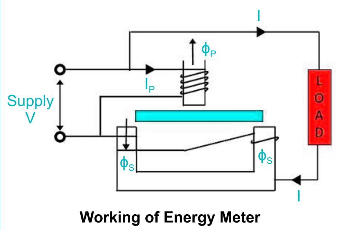
The working principle of an energy meter involves the conversion of electrical energy into mechanical energy or directly into a digital signal. The operating principle differs based on the type of meter used. Here is a basic explanation of the working principles for electromechanical and electronic energy meters:
- Electromechanical Energy Meter:
- Electromagnetic Induction: The core working principle of electromechanical meters is electromagnetic induction. When current flows through a conductor placed in a magnetic field, it experiences a force that makes it move. In an energy meter, the current-carrying coil is placed in the magnetic field created by a permanent magnet or another coil, causing a rotating disc.
- Rotation of Disc: The speed at which the disc rotates is proportional to the power consumed. This rotation is mechanically linked to the dials or counters that indicate the energy usage.
- Friction Brake: A brake mechanism is applied to the disc to limit its speed, ensuring that it does not rotate too quickly, and the readings remain accurate.
- Electronic Energy Meter:
- Voltage and Current Sensing: Electronic meters use voltage and current sensors to continuously measure the electrical parameters of the system.
- Digital Conversion: The measured analog signals (voltage and current) are fed into an analog-to-digital converter (ADC) that transforms the continuous signals into discrete digital signals.
- Microcontroller Processing: A microcontroller processes the digital signals, calculating the energy consumed in real-time. The calculated data is shown on a digital display and saved for later reference.
Construction of an Energy Meter
The construction of an energy meter can vary depending on the type (electromechanical, electronic, or smart). However, the general components include the following:
- Current Coil: This coil is placed in series with the load and carries the current to be measured. It generates a magnetic field that interacts with the magnetic field of the voltage coil, producing a mechanical torque in the case of electromechanical meters.
- Voltage Coil: The voltage coil produces a magnetic field that interacts with the one created by the current coil. The voltage coil generates a magnetic field that interacts with the magnetic field produced by the current coil.
- Rotating Disc (for electromechanical meters): The current and voltage coils generate a magnetic field that induces a torque on a metal disc. The disc rotates, and the speed of rotation is proportional to the power consumption. The mechanical motion of the disc drives the dials to display the energy used.
- Digital Display (for electronic meters): Instead of mechanical dials, electronic energy meters have a digital display that shows the energy consumption in numerical form. A microcontroller processes the data to update the display in real-time.
- Mechanical Dials: In older electromechanical meters, the disc’s motion is linked to a set of dials or gears that indicate the energy usage.
- Brake Mechanism: A friction brake mechanism is applied to slow down the rotation of the disc in electromechanical meters, ensuring the meter measures the energy consumption accurately.
- Transformer (optional): In some energy meters, especially for higher voltage systems, transformers are used to step down the voltage to safe, measurable levels.
Energy Meter Phasor Diagram
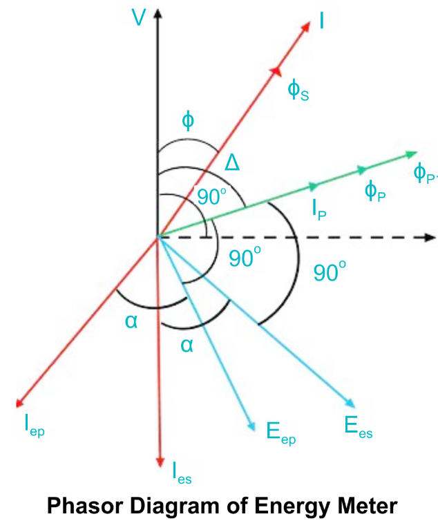
The phasor diagram is a graphical representation of the relationship between the voltage and current waveforms in an AC circuit. For energy meters, phasor diagrams help in understanding how the current and voltage are related, which is essential for accurate energy measurement.
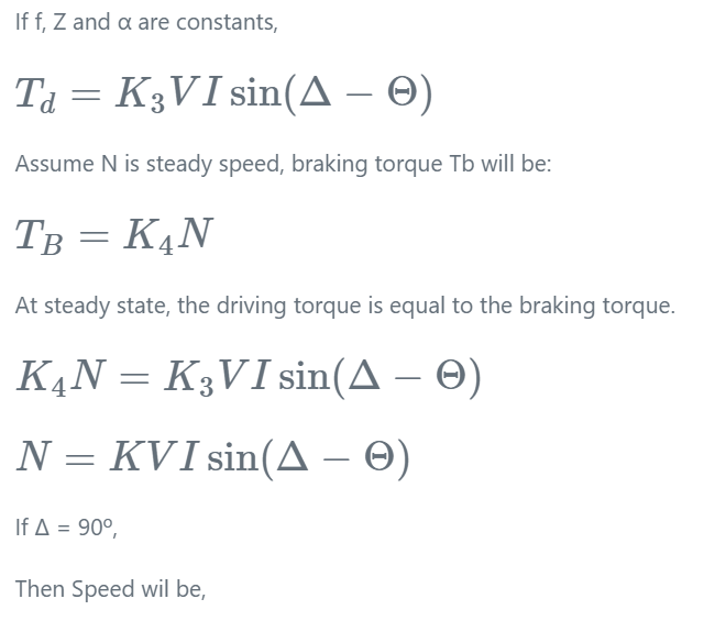
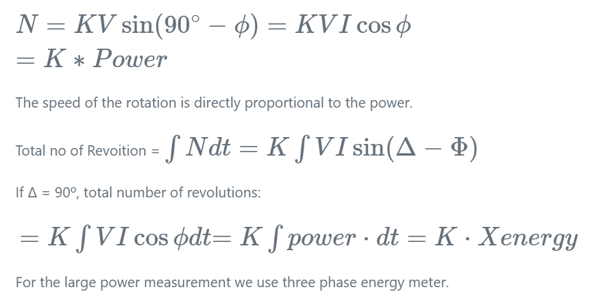
In a typical AC circuit, the voltage and current waveforms are sinusoidal but may be out of phase. The angle between the voltage and current phasors indicates the phase difference. For active power (real power), the voltage and current are in phase, and the power factor is unity (1). However, in most practical cases, the current and voltage are not perfectly in phase due to inductive or capacitive components, leading to a power factor less than 1.
The energy meter measures the product of voltage and current over time, which is then displayed as the energy consumption. The phase difference between the current and voltage is critical, as it influences the calculation of the true power (active power) that the energy meter records.
Conclusion
Energy meters are indispensable tools in modern electrical systems, providing accurate measurement and monitoring of electrical energy usage. Whether electromechanical, electronic, or smart meters, they all serve the primary function of measuring electrical consumption. Understanding the construction, working principles, and types of energy meters helps consumers and utilities optimize energy management and ensure efficient billing practices. Phasor diagrams are a useful tool in understanding the relationship between voltage and current, aiding in accurate energy measurement, particularly in AC circuits.
The post Energy Meter Definition, Types, Working, Construction & Diagram appeared first on ELE Times.
Analog IC vs Digital IC – Difference and Comparison
Integrated circuits (ICs) have revolutionized modern electronics, serving as the backbone of countless devices. Broadly, ICs are categorized into two main types: Analog ICs and Digital ICs. Understanding their differences and specific applications is essential for selecting the right components for various electronic systems. This article delves into the distinctions and comparisons between analog and digital ICs, highlighting their respective advantages, limitations, and use cases.
What are Analog ICs?
Analog ICs process continuous signals that vary over time and are used to manage real-world data such as sound, light, temperature, or pressure. These integrated circuits are crucial in scenarios that demand high precision and uncompromised signal quality.
Key Features of Analog ICs:
- Continuous Signal Processing: Operate with signals that have infinite values within a range.
- Signal Amplification and Conditioning: Amplify or modify analog signals for further processing.
- High Sensitivity: Analog ICs are ideal for handling small changes in signal amplitude.
Common Examples:
- Operational amplifiers (op-amps)
- Voltage regulators
- Analog-to-digital converters (ADCs)
- Audio amplifiers
What are Digital ICs?
Digital integrated circuits process discrete signals, encoding information in binary format, where data is represented as sequences of 0s and 1s. These ICs are integral to modern computing and communication systems.
Key Features of Digital ICs:
- Binary Signal Processing: Work with two distinct states, high (1) and low (0).
- Logical Operations: Perform arithmetic, logical, and control operations efficiently.
- Noise Immunity: Digital ICs demonstrate greater resilience to noise, making them more reliable in environments with high interference.
Common Examples:
- Microprocessors
- Memory chips (RAM, ROM)
- Logic gates
- Digital-to-analog converters (DACs)
Comparison Between Analog ICs and Digital ICs
| Aspect | Analog IC | Digital IC |
| Signal Type | Continuous signals | Discrete signals (binary) |
| Processing | Processes real-world, variable data | Processes binary data |
| Complexity | Simpler design | Higher complexity in circuits |
| Noise Sensitivity | More vulnerable to interference and distortions | More resistant to interference and noise disruptions |
| Applications | Audio, sensors, signal conditioning | Computing, storage, digital communication |
| Power Consumption | Generally higher for amplifiers | Lower for logic circuits |
| Accuracy | Depends on precision of components | High for binary operations |
| Speed | Limited by signal amplitude and frequency | Faster due to digital switching |
Hybrid ICs: Bridging the Gap
Modern systems often necessitate a combination of both analog and digital capabilities to function seamlessly. For instance, smartphones rely on analog ICs for signal acquisition (microphones, cameras) and digital ICs for processing (processors, memory). Hybrid ICs, which combine analog and digital components, are increasingly popular for such integrated applications.
Example:
- Analog-to-Digital Converters (ADCs) convert continuous analog inputs into a digital format, enabling their use in computational and processing systems.
- Digital-to-Analog Converters (DACs) take processed digital data and convert it back into analog signals for practical, real-world output.
Applications of Analog ICs
- Audio Equipment: Analog amplifiers and equalizers enhance sound quality in audio systems.
- Power Management: Voltage regulators and power amplifiers manage and stabilize power supplies.
- Sensors and Instrumentation: Analog ICs process data from temperature, pressure, and motion sensors.
Applications of Digital ICs
- Computing Devices: Microprocessors and memory chips drive computers and smartphones.
- Communication Systems: Digital signal processors (DSPs) enable data encoding, modulation, and transmission.
- Automation and Control: Logic circuits and microcontrollers power robotics and industrial automation.
Advantages and Disadvantages
Analog ICs:
- Advantages:
- Superior for real-world signal processing.
- Ideal for use in scenarios where maintaining high signal accuracy and integrity is essential.
- Disadvantages:
- More susceptible to interference and signal degradation.
- Larger power consumption for certain tasks.
Digital ICs:
- Advantages:
- High accuracy and noise immunity.
- Efficient for high-speed operations and complex computations.
- Disadvantages:
- Limited in handling real-world signals directly.
- Conversion to and from analog signals may introduce delays.
Conclusion
Analog and digital ICs serve distinct yet complementary roles in modern electronics. While analog ICs excel in processing real-world signals with precision, digital ICs dominate areas requiring speed, accuracy, and computational power. The synergy of these technologies, often realized in hybrid ICs, is driving innovation across industries such as healthcare, automotive, consumer electronics, and communication. Understanding the strengths and limitations of each type enables engineers and designers to create optimized and efficient electronic systems tailored to specific applications.
The post Analog IC vs Digital IC – Difference and Comparison appeared first on ELE Times.
Sparc the robot wiring
 | A homemade robot powered by arduino [link] [comments] |
NUBURU announces board and committee appointments
Voyant launches FMCW LiDAR sensor on a chip
DOE announces $179m funding for Microelectronics Science Research Centers
Сторінки

