Feed aggregator
First Solar endows Missouri S&T professorship in Critical Energy Materials
Dominating the Skies: DRDO’s UAV Revolution
From the high-altitude surveillance of the Himalayas to the tactical maneuvering on the border, DRDO-developed drones and UAVs are silently shaping the contours of India’s defense. This article delves into the impressive array of unmanned systems born from the ingenuity of DRDO, exploring their diverse roles, cutting-edge technologies, and the strategic impact they have on India’s evolving security landscape.
- Rustom Series
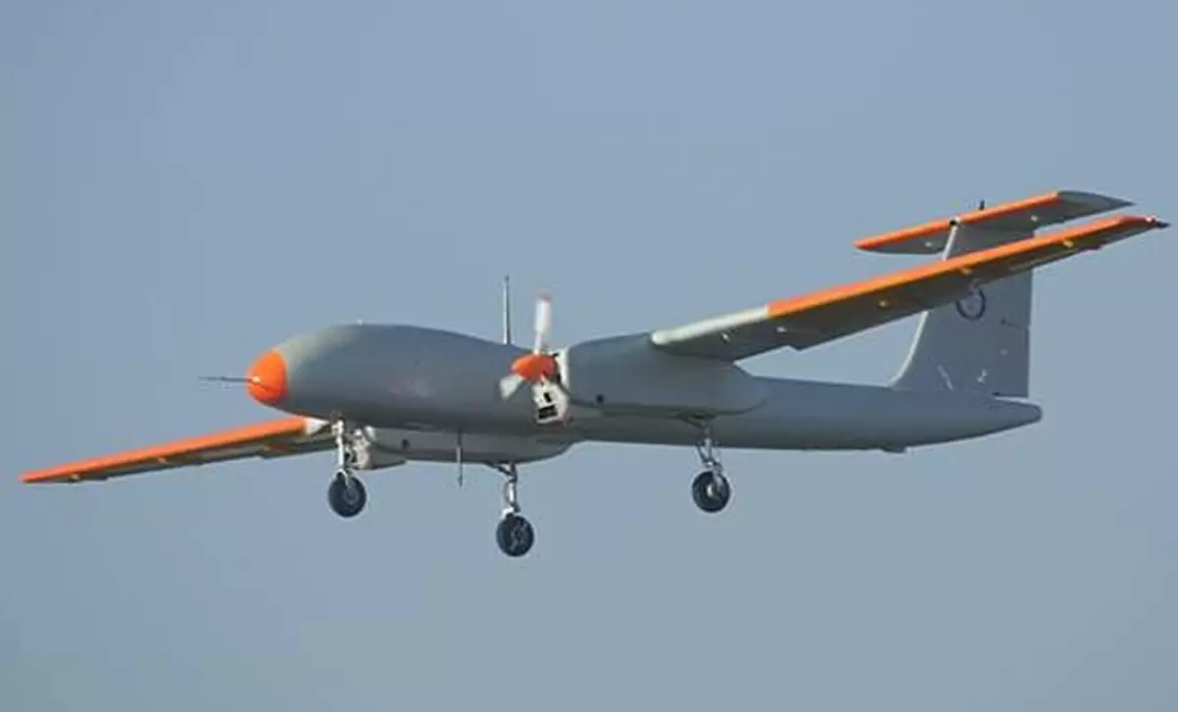 The Rustom series represents DRDO’s flagship UAV program, inspired by the National Aeronautical Laboratory’s (NAL) earlier designs. The series is named after Rustom Damania, a pioneer in Indian aerospace engineering. The Rustom series includes multiple variants tailored to specific missions:
- Rustom-I:
- Type: Medium-Altitude Long-Endurance (MALE) UAV
- Primary Use: Intelligence, Surveillance, and Reconnaissance (ISR)
- Key Features:
- Endurance: Up to 12 hours
- Payload capacity: 75 kg
- Operational altitude: 22,000 feet
- Applications: Border surveillance and reconnaissance missions
- Rustom-II (TAPAS-BH-201):
- Type: Advanced MALE UAV
- Primary Use: Long-endurance ISR missions with strike capabilities
- Key Features:
- Endurance: Over 24 hours
- Operational altitude: 35,000 feet
- Payload capacity: Up to 350 kg
- Status: Under extensive testing and trials for integration into the armed forces
- Rustom-H:
- Type: High-Altitude Long-Endurance (HALE) UAV
- Primary Use: Long-term surveillance and strategic ISR missions
- Status: Development phase
- Nishant
The Nishant series is a tactical Unmanned Aerial Vehicle (UAV) developed by India’s Defence Research and Development Organisation (DRDO). Specially designed for intelligence, surveillance, and reconnaissance (ISR) roles, Nishant was equipped with advanced electro-optic and infrared sensors. Launched via a hydro-pneumatic rail system, it played a crucial role in counter-insurgency and battlefield surveillance. Widely recognized for its operational effectiveness, Nishant marked a significant step in indigenous UAV development before being phased out for more advanced systems.
- Type: Tactical UAV
- Primary Use: Short-range ISR and battlefield surveillance
- Key Features:
- Launched via a mobile hydro-pneumatic rail launcher
- Payload: Electro-optic and infrared sensors
- Range: 160 km
- Endurance: 4.5 hours
- Notable Deployment: Widely used during counter-insurgency and border monitoring operations
- Status: Retired, replaced by more advanced systems
- Lakshya
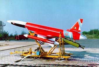 Lakshya is an advanced pilotless target aircraft developed to meet the needs of high-performance aerial target systems. Designed for simulating enemy threats during combat training and weapon evaluation, Lakshya offers remarkable versatility with features like remote control, pre-programmed flight paths, and high maneuverability. Its upgraded version, Lakshya-2, enhances operational capabilities, ensuring accurate replication of evolving aerial threats. This indigenously developed system underscores India’s prowess in defense technology innovation and continues to serve as a critical asset in the nation’s defense arsenal.
- Type: High-speed target drone
- Primary Use: Aerial target for training and weapon calibration
- Key Features:
- Operational altitude: 30,000 feet
- Speed: 0.7 Mach
- Applications: Simulating enemy aircraft for live-fire training
- Status: In active service, with multiple upgrades
- Abhyas
The DRDO Abhyas is an advanced high-speed expendable aerial target (HEAT) developed by the Defence Research and Development Organisation (DRDO) of India. Designed to simulate a variety of aerial threats for weapons testing and training, Abhyas features a radar cross-section (RCS) enhancer, an acoustic miss distance indicator (AMDI), and the ability to replicate different threat profiles. Launched using a twin-booster system, it operates on a gas turbine engine, offering high endurance and maneuverability. Abhyas exemplifies India’s commitment to indigenous defense technology development, supporting robust and realistic training scenarios for the armed forces.
- Type: High-speed expendable aerial target (HEAT)
- Primary Use: Testing surface-to-air and air-to-air missile systems
- Key Features:
- Turbojet engine for extended performance
- Maximum altitude: 5 km
- Applications: Weapon evaluation and air defense training
- Status: Under induction and operational use
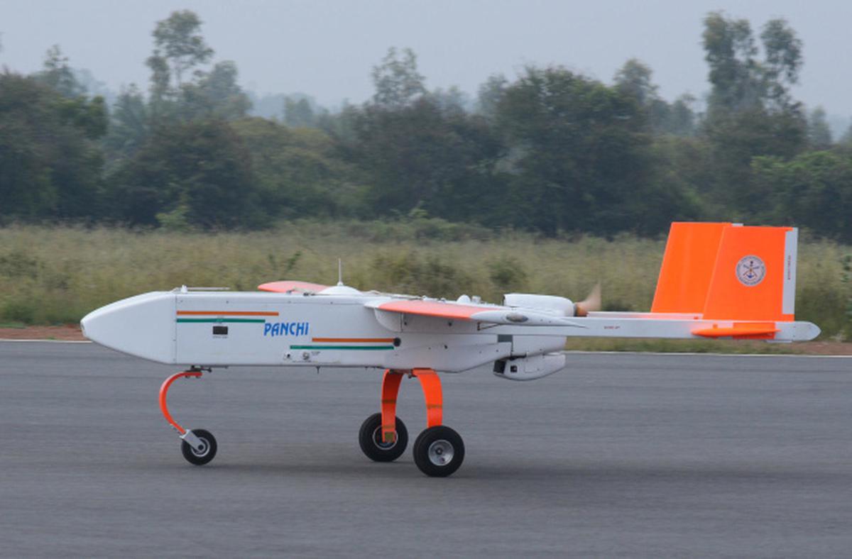
- Panchi
- Type: Wheeled version of the Nishant UAV
- Primary Use: ISR operations with a runway-based takeoff and landing capability
- Key Features:
- Enhanced flexibility compared to Nishant
- Longer endurance due to reduced launch constraints
- Netra (Developed in collaboration with IdeaForge)
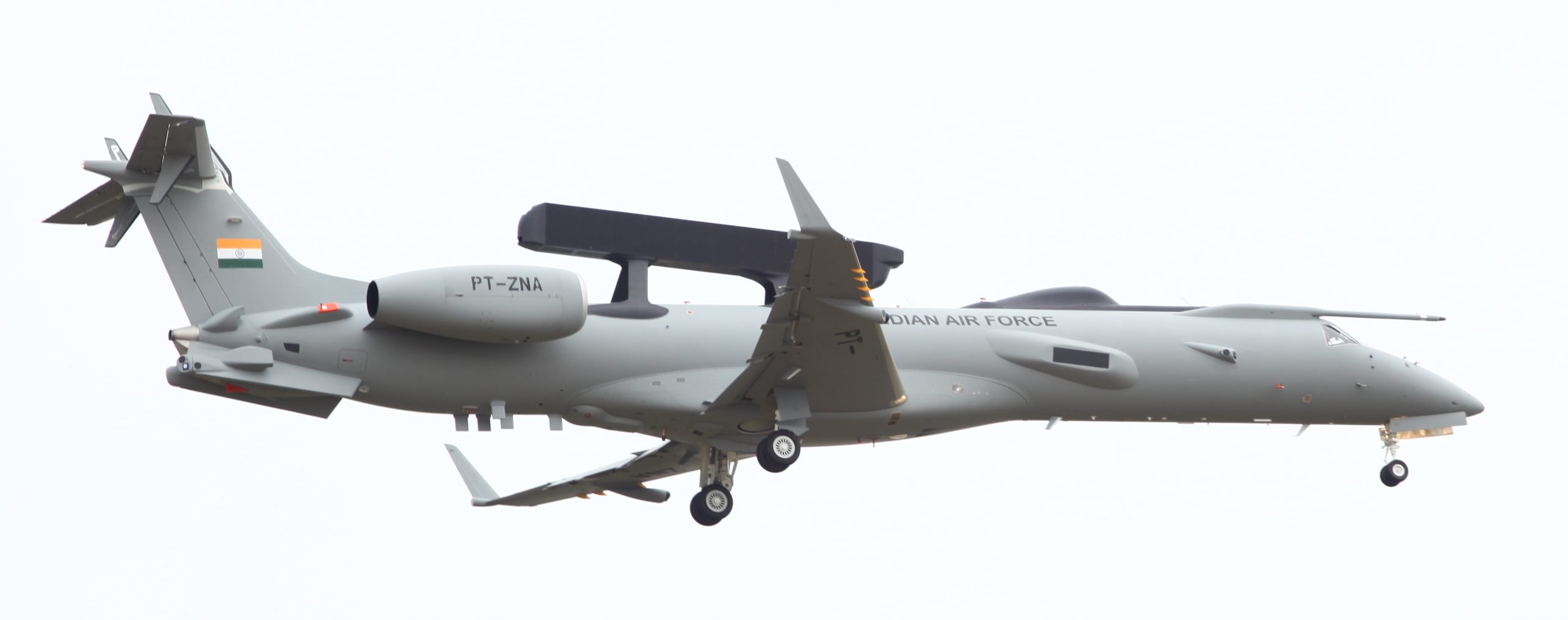
The DRDO Netra is India’s indigenous Airborne Early Warning and Control (AEW&C) system. Mounted on an Embraer EMB-145 platform, Netra features advanced radar and surveillance systems capable of tracking aerial and ground-based targets over a wide range. With a 240-degree coverage and state-of-the-art communication capabilities, it plays a vital role in enhancing situational awareness and supporting tactical operations.
- Type: Mini UAV
- Primary Use: Urban surveillance and crowd monitoring
- Key Features:
- Lightweight quadcopter design
- Real-time video surveillance capability
- Applications: Disaster management, border infiltration monitoring, search and rescue etc.
- Notable Usage: Extensively used during search-and-rescue operations and for monitoring sensitive areas
- Aura (Autonomous Unmanned Research Aircraft)
The AURA program represents India’s ambitious leap into developing an indigenous Unmanned Combat Aerial Vehicle (UCAV). Spearheaded by the Defence Research and Development Organisation (DRDO), AURA is designed for stealth and precision, capable of delivering strategic payloads with minimal detection. Envisioned with advanced composite materials and autonomous systems, it symbolizes a significant advancement in India’s defense technology, aiming to reduce reliance on imports and fortify the nation’s aerial combat capabilities.
- Type: Unmanned Combat Aerial Vehicle (UCAV)
- Primary Use: Stealth operations and precision strikes
- Key Features:
- Design: Flying wing configuration for stealth
- Payload: Precision-guided munitions and ISR equipment
- Status: Development phase with significant potential for high-impact defense missions
- Imperial Eagle
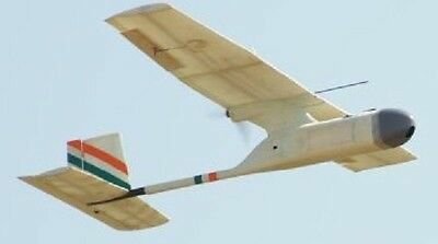
Imperial Eagle is an advanced tactical Unmanned Aerial Vehicle (UAV) developed in collaboration with private industry partners. Designed primarily for surveillance and reconnaissance, the Imperial Eagle is equipped with state-of-the-art sensors and communication systems to support military and paramilitary operations. Its compact design and high endurance make it ideal for monitoring sensitive areas, providing real-time intelligence to enhance operational effectiveness.
- Type: Tactical UAV
- Primary Use: Short-range reconnaissance
- Key Features:
- Lightweight and portable
- Applications: Counter-insurgency and tactical surveillance
- Status: Limited deployment, with potential for scaling
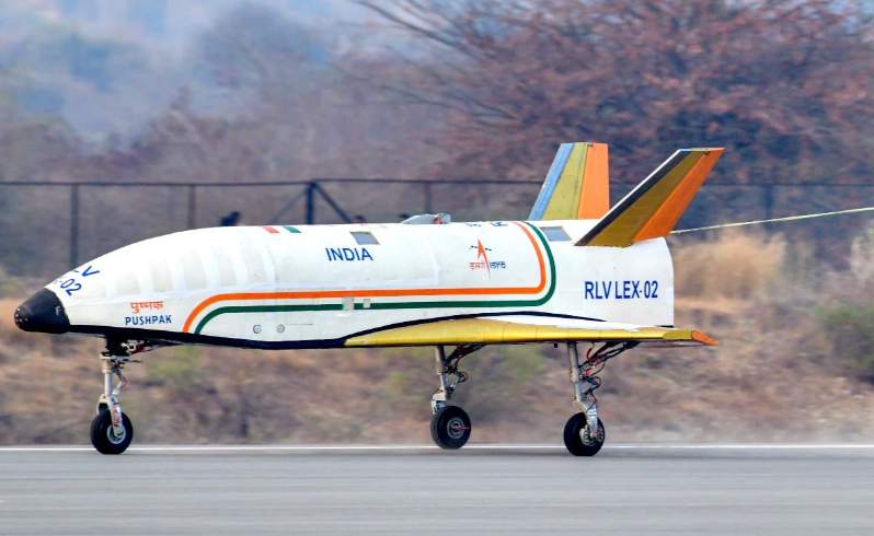
- Pushpak
The NAL/ADE Pushpak is an autonomous Unmanned Aerial Vehicle (UAV) jointly developed by the National Aerospace Laboratories (NAL) and the Aeronautical Development Establishment (ADE), divisions of DRDO. Designed for tactical operations, Pushpak is a lightweight, high-performance UAV primarily intended for surveillance, reconnaissance, and intelligence gathering. With advanced avionics, real-time data transmission capabilities, and robust design, it plays a vital role in enhancing situational awareness across varied terrains, underscoring India’s progress in indigenous UAV technology.
- Type: Fixed-wing UAV
- Primary Use: Environmental monitoring and ISR missions
- Key Features:
- Compact design for ease of deployment
- Applications: Disaster management and environmental surveys
Conclusion
India’s journey into UAV and drone technology, spearheaded by DRDO, reflects a bold vision of self-reliance and innovation in defense. From surveillance-focused UAVs like Nishant to cutting-edge systems like Aura, DRDO’s achievements showcase a blend of ingenuity and strategic foresight. These advancements not only strengthen India’s defense capabilities but also position the nation as a global contender in unmanned aerial systems. As DRDO continues to push the boundaries of technology, it paves the way for a future where Indian innovation becomes a cornerstone of national and global security.
The post Dominating the Skies: DRDO’s UAV Revolution appeared first on ELE Times.
Element Six unveils copper diamond composite to power advanced semiconductor devices
SemiQ launches QSiC 1700V series of high-reliability, low-loss SiC MOSFETs
VIPower full bridge with real-time diagnostics reduces complexity and cost of automotive drives
The VNH9030AQ integrated full-bridge DC motor driver handles diverse automotive uses including functional-safety applications. As well as integrating advanced diagnostics, the driver has a dedicated pin for real-time output status that saves external circuitry and slims the bill of materials.
With RDS(on) of 30mΩ per leg, the VNH9030AQ efficiently handles mid- and low-power DC motor driven applications such as door-control modules, washer pumps, powered lift gates, powered trunks, and seat adjusters.
Contributing to the driver’s high overall efficiency, and saving external components, integrated non-dissipative current-sense circuitry monitors the current flowing through the device to distinguish each motor phase. The standby power consumption is very low over the full operating temperature range, easing use in zonal controller platforms.
The VNH9030AQ integrates the high-side and low-side MOSFETs with gate drivers, diagnostics, and protection against overvoltage transients, undervoltage, short-circuit conditions, and cross conduction. Flexibility to configure the MOSFETs either in parallel or in series allows use in systems involving multiple motors or to meet other specific requirements.
The new driver is part of a family of devices that leverage ST’s latest VIPower M09 technology, which permits efficient, monolithic integration of power and logic circuitry. All products feature an innovative 6mm x 6mm thermally enhanced triple-pad QFN package designed for optimal underside cooling and share a common pinout to ease layout and software reuse.
The post VIPower full bridge with real-time diagnostics reduces complexity and cost of automotive drives appeared first on ELE Times.
Please forgive me
 | submitted by /u/Canadian_Rubles [link] [comments] |
✅ Оголошується конкурс на заміщення посад
Національний технічний університет України «Київський політехнічний інститут імені Ігоря Сікорського» оголошує конкурс на заміщення вакантних посад
Multi-solar panel interconnections: Mind the electrons’ directions

The concluding post in a series; here’s part 1 (covering the Energizer PowerSource Pro Battery Generator) and part 2 (discussing its companion 200W portable solar panel)…
Eagle-eyed readers may have already noticed, within the listing for the Energizer Solar Bundle I bought at the beginning of September (and returned shortly thereafter), the following prose:
Pick up another 200-watt solar panel on SideDeal to max out the solar capacity of 400W (but do take note of these instructions)
That I did, for an incremental $179.99. It was (past tense usage because I ended up returning it, too) a “Duracell Heavy Duty 200-Watt Briefcase Solar Panel”, and it also came from Battery Biz. Here are some “stock” images:


Along with a bullet list of specs:
- Brand: Duracell
- Material: Monocrystalline Silicon [editor note: claimed conversion efficiency of 22%]
- Dimensions (unfolded): 55.2 x 36.5 x 1.3 in
- Item Weight: 36.2 lbs
- Maximum Power Point Voltage: 18.6 V
- Maximum Power Point Current: 10.8 V
- Open Circuit Voltage: 22.8 V
- Short Circuit Current: 11.2 A
- Maximum System Voltage (Vmax): 1000VDC
- Normal Operating Cell Temperature (NOCT): 45±2°C
- Temperature Range (°C): -40°C~+85°C
- Power Tolerance: ±5%
- Application Class: Class A
- Included Components: Panel
- Maximum Power: 200 Watts
- Manufacturer: Duracell
When it arrived, the outer packaging was…err…already breached:


Thankfully, the box inside was still intact:

although, as you may have already noticed, the product image on the front didn’t match the “stock” shots, which left me a bit disconcerted before I even opened it.
Here’s the box backside:

Take the “unfolded” dimensions listed in the earlier bullet list, divide the largest by two, and you end up with an approximation of the data shown in this closeup image, which was reassuring:

Open the box, pull out the hefty contents (the promotional prose claims that you can “Experience the convenience of home no matter where you are with our lightweight and foldable solar panel” (foldable = yes, lightweight = not), and the “Zippered Carrying Case with Handle” conceptualized in the previous photo’s graphic is the first thing you’ll come across:

Chug a can of spinach, unzip the case and huff, puff and pull the bulky panel out:

Now undo the clips on the “handle” edge and unfold it:

Like I said, it looks nothing like the “stock” photos, although it ended up being fully functional.
I only realized after returning it that I’d neglected to snap a photo of the backside, so another closeup of the box will have to do:

The cable coming out of the back of the panel terminates in a pair of MC4 connectors:

The also-included adapter cable converts the MC4s into an Anderson PowerPole PP15-45 connector for use with the Energizer PowerSource Pro Battery Generator (along with other Anderson-compatible battery-based products, of course, including Duracell’s own):

Its measured open-circuit output voltage closely approximated the earlier-listed max spec:

and it did charge up the PowerSource Pro reasonably speedily in direct sunlight:

Had I been able to as-intended combine it with the Energizer solar panel, of course, the combo likely would have been speedier still from a charging-rate standpoint. But from my earlier writeup, you already know about the connector woes that prevented such an arrangement and resultant experiment. And since the other gear I’d bought ended up being subpar and sent back to the retailer, I had no other use for this panel, either, so it got returned for full refund, too.


That all said, for the remainder of this writeup I’d like to delve a bit deeper into the suggested dual-panel configuration linked to within the initial Meh teaser and replicated here:

To a first conceptual approximation, you can think of two (or more) solar panels as batteries. Connect them in series and you boost the effective output voltage. Tether them in parallel, conversely, and the aggregate output current goes up. That said, as my research has enlightened me, they also exhibit important differences from batteries in both possible configurations. These variances derive from two fundamental keywords: batteries (ironically) and shade (i.e., “dark”).
Rarely if ever is the solar illumination of a single panel uniform, far from across multiple panels. This inconsistency is due to various factors, such as imperfect orientation versus the sun’s position of the moment in the sky, and the aforementioned shading caused by clouds, trees, and other partially-to-fully obscuring intermediate objects. For series-interconnected panels, illumination inconsistency means that the effective current you’ll be able to squeeze out of a multi-panel configuration is constrained by the least-illuminated panel in the chain. And you’ll of course also want to make sure that the aggregate voltage generated by the multi-panel series arrangement in full illumination doesn’t exceed the max input voltage of whatever it’s driving.
What about multi-panel parallel hookups such as the one recommended in the Energizer documentation? To tether them together requires a combiner cable such as this one I’d bought:

Minimally, you’ll want to ensure that the output voltages of both panels match (for reasons you’ll soon understand) and, this time, that the aggregate current generated by the multi-panel parallel arrangement in full illumination won’t exceed the max input current of whatever it’s driving. “What it’s driving” in my particular case was the Energizer PowerSource Pro Battery Generator, supposedly. Which is where the words “shade” and “battery” fully come to the fore.
Assume first that the combiner cable simply merges the panels’ respective positive and negative feeds, with no added intermediary electronics between them and the electrons’ intended destination. What happens, first, if all the parallel-connected panels are in shade (or to my earlier “dark” wording surrogate, it’s nighttime)? If the generator is already charged up, its battery pack’s voltage potential will be higher than that of the panels themselves, resulting in possible reverse current flow from the generator to the panels. Further, what happens if there’s an illumination discrepancy between the panels? Here again there’ll be a voltage potential differential, this time between them. And so, in this case, even if they’re still charging up the generator’s batteries as intended, there’ll also be charging-rate-inefficient (not to mention potentially damaging; keep reading) current flow from one panel to the other.
The result, described in this crowded diagram from the same combiner-cable listing on Amazon:

is what’s commonly referred to as a “hotspot” on one or all panels. Whether or not it negatively impacts panel operating lifetime is, judging from the online discussions I’ve auditioned, a topic of no shortage of debate, although I suspect that at least some folks who are skeptical are also naïve…which leads to my next point: how do you prevent (or at least minimize) reverse current flow back to one or both panels? With high power-tolerant diodes, I’ll postulate.
Those folks who think you can direct-connect multiple panels in parallel with nothing but wire? What I suspect they don’t realize is that there are probably reverse current-suppressing diodes already in the panels, minimally one per but often also multiple (since each panel, particularly for large-area models, is comprised of multiple sub-panels stitched together within the common frame). The perhaps-already-obvious downside of this approach is that there’s a forward-bias voltage drop across each diode, which runs counter to the aspiration of pushing as much charge power as possible to the destination battery pack. To that point, I suspect this is precisely what this Amazon reviewer is experiencing (also check out the video at the source link):
So I can draw about 86 to 92 watts to my Jackery with the cable from the solar panel but as soon as I plug in the splitter, it drops down to about 60-70 watts. When I plug in both 100 watt solar panels, I get about 120-130 watts. So the splitter somehow loses power when hooked up.
If you look closely at the earlier “crowded diagram” you can see a blurry image of what the combiner cable’s circuitry supposedly looks like inside:

Prior to starting this writeup, I’d returned the original combiner cable I bought, since due to my in-parallel return of the Duracell and Energizer devices, I no longer needed the cable, either. But I’ve just re-bought one, to satisfy my own “what’s inside” research-induced curiosity, which I’ll share with you in a teardown to come. Until then, I welcome your thoughts in the comments!
—Brian Dipert is the Editor-in-Chief of the Edge AI and Vision Alliance, and a Senior Analyst at BDTI and Editor-in-Chief of InsideDSP, the company’s online newsletter.
Related Content
- The Energizer 200W portable solar panel: A solid offering, save for a connector too fragile
- Energizer’s PowerSource Pro Battery Generator: Not bad, but you can do better
- Experimenting with a modern solar cell
- Solar-mains hybrid lamp
- Beaming solar power to Earth: feasible or fantasy?
The post Multi-solar panel interconnections: Mind the electrons’ directions appeared first on EDN.
EPC launches 3-phase BLDC motor drive inverter reference design
Lynred launches Eyesential SW shortwave IR sensor for machine vision
"Корпус та дискурс" на ФЛ
В КПІ ім. Ігоря Сікорського відбулась ІV Міжнародна науково-практична онлайн-конференція "Корпус та дискурс", організована кафедрою англійської мови технічного спрямування №1 факультету лінгвістики. Захід об'єднав понад 100 учасників з різних країн світу – аспірантів, молодих дослідників, викладачів і академіків.
If you can't submit to this sub because you're getting a "You can't contribute to this community yet" message, please know that it's Reddit doing it, not the sub.
If you have an on-topic submission *, please tell the moderators and we can post it for you.
(*) The focal point of a submission must be component-level electronic engineering, design, news, and circuits (with at least one active element: a semiconductor or a vacuum tube/valve).
(*) Questions not allowed.
[link] [comments]
Anatomy of MCUs for motor control

Control MCUs increase performance and efficiency of motor control and power conversion systems by enabling real-time control of systems that need to respond to real-time events with minimal delay and low utilization. These MCUs are targeted at battery-powered applications with motors, large appliances, HVAC units, and power supplies for server farms and cloud computing centers.
Read full story at EDN’s sister publication, Planet Analog.
Related Content
- Advances in MCUs ease motor control
- Optimizing MCUs for EV Motor Control
- Microcontrollers for Motor Control Systems
- MCUs specializing in motor control, power conversion
- Designer’s Guide to High-Performance Motor Control for Robotics
The post Anatomy of MCUs for motor control appeared first on EDN.
Thorlabs acquires strategic partner Praevium Research
Турнір з футзалу пам’яті Віталія Івановича Молчанова 2025
Уже вшосте в спорткомплексі КПІ ім. Ігоря Сікорського відбувся щорічний традиційний турнір з футзалу пам’яті Віталія Івановича Молчанова — справжнього професіонала, видатного освітянина, професора факультету електроніки й до того ж — багаторічного голови Профкому працівників Київської політехніки. Саме профком нашого університету і проводить цей турнір.
Vacuum Tubes (1943) [found footage; covers basic tube and RF rx/tx theory; I found it quite enjoyable so thought to share]
![Vacuum Tubes (1943) [found footage; covers basic tube and RF rx/tx theory; I found it quite enjoyable so thought to share] Vacuum Tubes (1943) [found footage; covers basic tube and RF rx/tx theory; I found it quite enjoyable so thought to share]](https://external-preview.redd.it/_YCih_2ayM0fcaqL6gFvEX_VZVxY-TQnyRAkVto2xm8.jpg?width=320&crop=smart&auto=webp&s=2a450cdbdcd0411c69a2ab1e1a30ef60d67d77ae) | submitted by /u/russellmzauner [link] [comments] |
US CHIPS Incentives Program awards finalized for Corning, Edwards Vacuum and Infinera
A beginner’s guide to power of IQ data and beauty of negative frequencies – Part 2
 Introduction and editor’s note
This is a two-part series where DI authors Damian and Phoenix Bonicatto explore the IQ signal representation and negative frequencies. Part 1 explains the commonly used SDR IQ signal representation and negative frequencies without the complexity of math.
This final part (Part 2) presents a device that allows you to play with and display live SDR signal spectrums with negative frequencies.
Wow the engineering world with your unique design: Design Ideas Submission Guide
Defining real and imaginary signalsLet’s start off with something I left out on purpose in Part 1, there are two more terms we will use: A “real” signal is a term used for the signal represented by the I data. “Imaginary” signal is the term used for the signal represented by the Q data. I left them out until now as they add to the obfuscation of the discussion. Just take them at face value as there is nothing imaginary about an “imaginary” signal.
The “I/Q Explorer” designOkay, so what we are going to make is an Arduino Nano based device that can generate “real” and “imaginary” data (I and Q samples) per your settings of frequency, amplitude, and phase. Then it will display a spectrum showing positive and negative frequencies. We will not use the FFT feature of your scope, we will generate the spectrum in the MCU and send it out to the oscilloscope to form a trace in the shape of the spectrum. In fact, we will generate a spectrum for the real signal, imaginary signal, and the magnitude of the combination (this is the square root of the sum of the squares of the real and imaginary signals).
We will refer to this design as the I/Q Explorer (Figure 1).
 Figure 1 The final I/Q Explorer design with an LCD for displaying menu items and values and a toggle switch to switch the scope between the time and frequency domains.
Let’s look at the schematic in Figure 2.

Figure 2 The schematic of the IQ Explorer device with an Arduino Nano, 4×20 LCD, two rotary encoders, a simple toggle switch, three analog outputs, three lines to go to the scope probes, a digital output, and BNC connectors.
You can see the I/Q Explorer has a relatively simple schematic. It’s based on an Arduino Nano and uses a 4×20 LCD for displaying menu items and values. The two rotary encoders are used to navigate through the menu and to change values. A simple toggle switch is used to change the scope view from the time domain to frequency domain. There are three analog outputs, created using PWM outputs and single pole RC low-pass filters. The three lines go to the scope probes (you don’t need to connect all three if you don’t have a 4-channel scope). There is also a digital output used as a trigger to sync the scope to the analog outputs. The only other electrical parts are two BNC connectors which can be used if you want to get signals from a signal generator, instead of the internal generated signals.
The test stand itself can be easily 3D printed (a link to the 3D files and Arduino code are at the end of the article). The test stand provides a place to mount the LCD, rotary encoders and the time/frequency switch. Two BNC connectors can be installed on the left side. On the right side is a place to install four wires that will be used to clip the scope probe on (you also need to clip one of the leads to a ground). The rest on the circuitry can be laid out on a small solderless breadboard. The breadboard then fits on the back of the test stand. A document showing more images, BOM, and additional instructions can be found in the download from the link at the end of the article.
Using the I/Q ExplorerOk, what can you do with it now? First, the left side of the test stand has four bare wires that are used to connect the scope probes (also connect one scope probe ground to digital ground on the breadboard. The top wire is the real data, the next one down is the imaginary data, then the magnitude, and the bottom one is the trigger. Connect the real, imaginary, and magnitude to the three inputs of your scope (if you only have a two-channel scope, you can connect the real and imaginary only, without missing much). The trigger can be connected to the last scope channel or to the external trigger of your scope.
Now, set the Freq/Time switch to Freq. On your scope, set the vertical to 2v/div, for each of the inputs. Also set the sweep to 20ms/div.
Now you can power the system via the USB connection on the Arduino Nano. Spread out the traces on the scope and set the scope to trigger using the trigger input. You can now hide the trigger trace. The traces should look like what we see in Figure 3.

Figure 3 The starting spectrum from -2500 to +2500 Hz where there is signal energy at both -1500 and +1500 Hz.
Now adjust the horizontal position so the traces are centered. Ignore the time axis on the bottom and the voltage axis on the right side—they are irrelevant (turn them off if your scope has such a feature). The left-to-right axis is frequency with -2500 Hz on the left side and +2500 Hz on the right side. DC or 0 Hz is the center line. (On scopes with 10 major horizontal markings, each major marking measures off 500 Hz increments.) Vertical is only a relative, auto-scaled, value so it is best to keep the volts/div the same for the real, imaginary, and magnitude traces. So, in Figure 3 you can see we have signal energy at both +1500 Hz and -1500 Hz. (Note, on boot up the real signal is 100 while the imaginary amplitude is 0.)
You will see a menu on the I/Q Explorer LCD. Rotating the left rotary encoder will allow you to move up and down in the menu. The right rotary encoder allows you to change the values of the menu item next to the flashing cursor (second line from the top of the LCD). In the menu you can change the frequency, amplitude and the phase of the real (I data) or imaginary (Q data) signals.) Note that changing the frequency of either the real or imaginary will change the other—they need to be at the same frequency.) The menu also has items to print data, plot data, turn on/off windowing, turn on/off a mixer, and change the source for the FFT from the internal generated data to external signal from a signal generator.
As a sanity check, Figure 4 is a plot of the real output from a simulation package using the same signals, sample rate, and number of samples. These are as follows: The real signal used has an amplitude of 100 and the imaginary signal has an amplitude of 0. The frequency of both is 1500 Hz. The sample rate is 5000 samples/second and the number of samples used in the FFT is 64.

Figure 4 Real FFT simulation using the same settings where the real signal has an amplitude of 100, the imaginary signal has an amplitude of 0, the frequency of both is 1500 Hz, the sample rate is 5000 samples/second, and the number of samples used in the FFT is 64.
You can see that the real signal matches nicely.
Adjusting real and imaginary signal settingsLet’s change the imaginary signal so it has the same amplitude as the real signal. Set the imaginary amplitude to 100. Now we get the following in Figure 5.

Figure 5 The FFT when imaginary and real amplitudes are the same (set to 100).
You can see we only have a signal at +1500 Hz…there is no negative frequency component.
If we flip the Freq/Time to “Time” you will be able to see the time domain samples used to generate the FFT, without adjusting anything on the scope.
Mixer modeNow let’s try quadrature (complex-to-complex) mixing. Move down in the menu and turn on “Mixer” (more on moving and adjusting settings in the download). This will do the mix using the real and imaginary signals you have sets, and a fixed signal having its real and imaginary setting of 1000 Hz, and amplitudes of 100 and phases set to 0. What you will at first is shown in Figure 6.

Figure 6 Quadrature mixing of 1500 Hz with 1000 Hz showing the signal at 500 Hz and an image created at 2000 Hz.
You can see two things. First, the signal is now at 500 Hz, the difference of 1500 Hz from our signal and the 1000Hz from the mix signal. Second, there is an image created at 2000 Hz (1500 Hz + 500 Hz) but it has been removed by the mathematics of the mixer.
Next change the frequency of the real or imaginary signal (remember one will change the other) to 500 Hz. Also note, as you turn the dial, the FFT frequency will slide down as you approach 500 Hz. And as you go past 1000 Hz you will see the FFT in the negative frequency area. When you get to 500 Hz you will see this in Figure 7.

Figure 7 Quadrature (complex-to-complex) mixing of 500 Hz with 1000 Hz.
You now have generated a negative frequency—as simple as that.
Note that you can also see the plot, of any of the displayed FFTs, on the PC by using the “Serial Plot” selection. You can also get a view of the numerical data by using the “Serial Print Data” selection.
More fun IQ manipulationSo now that you’ve seen a few examples, you can explore I/Q data and quadrature mixing by changing things like the amplitude of the real and/or imaginary signals. Also, try changing the phase of signals. After you get a grasp of that try changing the phase of either. To get a real handle on this, see if you can manipulate the trig equations to better understand how you get to that FFT. The system also has a windowing function, you can play with, that adjusts amplitudes of the data points before the FFT is calculated (for those who know these things, it is a Hann window).
Remember, you can also use actual external signals, such as those from a two-channel signal generator, to perform the same tests. You’ll note though, the FFTs are not quite as stable. There is more information on that in the downloadable notes.
One last thought; you’ll find lots of discussion on whether negative frequencies are real (in the traditional sense) or not. My two cents is they are not physically real as they cannot be transmitted as a single waveform, but they are a very nice mathematical construct that allows us to manipulate the signals that we can receive. Let the arguing begin.
To download 3D printable files and document containing more operating info, a BOM, and extra photo, visit: https://makerworld.com/en/models/1013533#profileId-993290
The Arduino Nano code can be found at: Arduino Nano code can be found at: https://github.com/DamianB2/IQ_Explorer
Damian Bonicatto is a consulting engineer with decades of experience in embedded hardware, firmware, and system design. He holds over 30 patents.
Phoenix Bonicatto is a freelance writer.
Related Content
- A beginner’s guide to power of IQ data and beauty of negative frequencies – Part 1
- Exploring software-defined radio (without the annoying RF) – Part 1
- Exploring software-defined radio (without the annoying RF)—Part 2
- SDR Basics Part 3: Transmitters
- The virtual reality of 5G – Part 2 (measurements)
- Ultra-wideband I/Q demodulator improves receiver performance
The post A beginner’s guide to power of IQ data and beauty of negative frequencies – Part 2 appeared first on EDN.
Антикорупційний комікс від студенток КПІ: від ідеї до перемоги у всеукраїнському конкурсі
У молодіжному творчому конкурсі "Разом проти корупції! Твоє бачення має значення", що проводився Міністерством оборони України з нагоди Міжнародного дня боротьби з корупцією, друге місце вибороли студентки другого курсу факультету соціології і права КПІ ім.


