Новини світу мікро- та наноелектроніки
4 bit full Adder
 | I've assembled this 4 bit full adder with logic ics. [link] [comments] |
Infineon’s CoolGaN technology used in Anker’s new-generation 160W prime charger
A seldom-seen component: a snubber is a resistor and a capacitor in series. Placed across a switch or relay contact to suppress the arc (AC or DC).
 | submitted by /u/Electro-nut [link] [comments] |
Power Tips #147: Achieving discrete active cell balancing using a bidirectional flyback

Efficient battery management becomes increasingly important as demand for portable power continues to rise, especially since balanced cells help ensure safety, high performance, and a longer battery life. When cells are mismatched, the battery pack’s total capacity decreases, leading to the overcharging of some cells and undercharging of others—conditions that accelerate degradation and reduce overall efficiency. The challenge is how to maintain an equal voltage and charge among the individual cells.
Typically, it’s possible to achieve cell balancing through either passive or active methods. Passive balancing, the more common approach because of its simplicity and low cost, equalizes cell voltages by dissipating excess energy from higher-voltage cells through a resistor or FET networks. While effective, this process wastes energy as heat.
In contrast, active cell balancing redistributes excess energy from higher-voltage cells to lower-voltage ones, improving efficiency and extending battery life. Implementing active cell balancing involves an isolated, bidirectional power converter capable of both charging and discharging individual cells.
This Power Tip presents an active cell-balancing design based on a bidirectional flyback topology and outlines the control circuitry required to achieve a reliable, high-performance solution.
System architectureIn a modular battery system, each module contains multiple cells and a corresponding bidirectional converter (the left side of Figure 1). This arrangement enables any cell within Module 1 to charge or discharge any cell in another module, and vice versa. Each cell connects to an array of switches and control circuits that regulate individual charge and discharge cycles.
 Figure 1 A modular battery system block diagram with multiple cells a bidirectional converter where any cell within Module 1 can charge/discharge any cell in another module. Each cell connects to an array of switches and control circuits that regulate individual charge/discharge cycles. Source: Texas Instruments
The block diagram in Figure 2 illustrates the design of a bidirectional flyback converter for active cell balancing. One side of the converter connects to the bus voltage (18 V to 36 V), which could be the top of the battery cell stack, while the other side connects to a single battery cell (3.0 V to 4.2 V). Both the primary and secondary sides employ flyback controllers, allowing the circuit to operate bidirectionally, charging or discharging the cell as required.

Figure 2 A bidirectional flyback for active cell balancing reference design. Source: Texas Instruments
A single control signal defines the power-flow direction, ensuring that both flyback integrated circuits (ICs) never operate simultaneously. The design delivers up to 5 A of charge or discharge current, protecting the cell while maintaining efficiency above 80% in both directions (Figure 3).
Figure 3 Efficiency data for charging (left) and discharging (right). Source: Texas Instruments
Charge mode (power from Vbus to Vcell)In charge mode, the control signal enables the charge controller, allowing Q1 to act as the primary FET. D1 is unused. On the secondary side, the discharge controller is disabled, and Q2 is unused. D2 serves as the output diode providing power to the cell. The secondary side implements constant-current and constant-voltage loops to charge the cell at 5 A until reaching the programmed voltage (3.0 V to 4.2 V) while keeping the discharge controller disabled.
Discharge mode (power from Vcell to Vbus)Just the opposite happens in discharge mode; the control signal enables the discharge controller and disables the charge controller. Q2 is now the primary FET, and D2 is inactive. D1 serves as the output diode while Q1 is unused. The cell side enforces an input current limit to prevent discharge of the cell above 5 A. The Vbus side features a constant-voltage loop to ensure that the Vbus remains within its setpoint.
Auxiliary power and bias circuitsThe design also integrates two auxiliary DC/DC converters to maintain control functionality under all operating conditions. On the bus side, a buck regulator generates 10 V to bias the flyback IC and the discrete control logic that determines the charge and discharge direction. On the cell side, a boost regulator steps the cell voltage up to 10 V to power its controller and ensure that the control circuit is operational even at low cell voltages.
Multimodule operationFigure 4 illustrates how multiple battery modules interconnect through the reference design’s units. The architecture allows an overcharged cell from a higher-voltage module, shown at the top of the figure, to transfer energy to an undercharged cell in any other module. The modules do not need to be connected adjacently. Energy can flow between any combination of cells across the pack.

Figure 4 Interconnection of battery modules using TI’s reference design for bidirectional balancing. Source: Texas Instruments
Future improvementsFor higher-power systems (20 W to 100 W), adopting synchronous rectification on the secondary and an active-clamp circuit on the primary will reduce losses and improve efficiency, thus enhancing performance.
For systems exceeding 100 W, consider alternative topologies such as forward or inductor-inductor-capacitor (LLC) converters. Regardless of topology, you must ensure stability across the wide-input and cell-voltage ranges characteristic of large battery systems.
Modern multicell battery systems.The bidirectional flyback-based active cell balancing approach offers a compact, efficient, and scalable solution for modern multicell battery systems. By recycling energy between cells rather than dissipating this energy as heat, the design improves both energy efficiency and battery longevity. Through careful control-loop optimization and modular scalability, this architecture enables high-performance balancing in portable, automotive, and renewable energy applications.
 Sarmad Abedin is currently a systems engineer with Texas Instruments, working in the power design services (PDS) team, working on both automotive and industrial power supplies. He has been designing power supplies for the past 14 years and has experience in both isolated and non-isolated power supply topologies. He graduated from Rochester Institute of Technology in 2011 with his bachelor’s degree.
Related Content
- Active balancing: How it works and what are its advantages
- Achieving cell balancing for lithium-ion batteries
- Lithium cell balancing: When is enough, enough?
- Product How-To: Active balancing solutions for series-connected batteries
The post Power Tips #147: Achieving discrete active cell balancing using a bidirectional flyback appeared first on EDN.
ECMS applications make history, cross Rs. 1 lakh crore in investment applications
Union Minister for Electronics and IT Ashwini Vaishnaw announced that the government has received investment applications worth nearly 1 lakh 15 thousand, 351 crore rupees under the Electronics Component Manufacturing Scheme (ECMS) against the targeted 59 thousand 350 crore rupees. The union minister made the announcement during a media briefing in New Delhi after the last date for applications was closed on November 27, 2025. He credited the 11 years of trust in the system which is now expected to drive investment, employment generation, and production.
Additionally, he added that, against a production target of 4 lakh 56 thousand and 500 crore rupees, production estimates of over 10 lakh crore rupees have been received.
The post ECMS applications make history, cross Rs. 1 lakh crore in investment applications appeared first on ELE Times.
AI-Driven 6G: Smarter Design, Faster Validation
Courtesy: Keysight Technologies
| Key takeaways: Telecom companies are hoping for quick 6G standardization followed by a rapid increase in 6G enterprise and retail customers, with AI being a key enabler:
● Artificial intelligence (AI) and machine learning (ML) are expected to become essential and critical components of the 6G standards, scheduled for release in 2028 or 2029. ● Engineers in 6G and AI could take products to market quickly by understanding the potential benefits of AI / ML for 6G design validation. |
The 6G era is poised to be fundamentally different, it may potentially be the first “AI-native” iteration of wireless telecom networks. With extensive use of AI expected in 6G, engineers face an unprecedented challenge: How do you validate a system that is more dynamic, intelligent, and faster than anything before it?
This blog gives insights into 6G design validation using AI for engineers working in communication service providers, mobile network operators, communication technology vendors, and device manufacturers.
We explain the new applications that 6G and AI could unlock, the AI techniques you’re likely to run into, and how you could use them for designing and testing 6G networks.
What are the key use cases that 6G and AI will enable together?
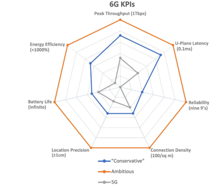
Figure 1. 6G conservative and ambitious goals versus 5G goals (Image source: How to Revolutionize 6G Research With AI-Driven Design)
The two engines of 6G and AI are projected to power exciting new use cases like real-time digital twins, smart factories, highly autonomous mobility, holographic communication, and pervasive edge intelligence.
These are among the major innovations that the International Telecommunication Union (ITU) and the Third Generation Partnership Project (3GPP) envision from 6G and AI. Let’s examine these key use cases for AI in 6G and 6G for AI in 2030 and beyond.
Real-time digital twins using 6G and AI
With promises of ubiquitous deployment, high data rates, and ultra-low latency, 6G and AI could create precise real-time representations of the physical world as digital twins.
Digital twins will be powerful tools for modeling, monitoring, managing, analyzing, and simulating all kinds of physical assets, resources, environments, and situations in real time.
Digital twin networks could serve as replicas of physical networks, enabling real-time optimization and control of 6G wireless communication networks. Proposed 6G capabilities like integrated sensing and communication (ISAC) could efficiently synchronize these digital and physical worlds.
Smart factories through 6G and AI
6G and AI have the potential to support advanced industrial applications (“industrial 6G”) through reliable low-latency connections for ubiquitous real-time data collecting, sharing, and decision-making. They could enable full automation, control, and operation, leveraging connectivity to intelligent devices, industrial Internet of Things (IoT), and robots. Private 6G networks may effectively streamline operations at airports and seaports.
Autonomous mobility via 6G and AI
6G and AI are set to enhance autonomous mobility, including self-driving vehicles and autonomous transport based on cellular vehicle-to-everything (C-V2X) technologies. This involves AI-assisted automated driving, real-time 3D-mapping, and high-precision positioning.
Holographic communication over 6G
6G and AI data centers could enable immersive multimedia experiences, like holographic telepresence and remote multi-sensory interactions. Semantic communication, where AI will try to understand users’ actual current needs and adapt to them, could help meet the demands of data-hungry applications like holographic communication and extended reality, transmitting only the essential semantics of messages.
Pervasive edge AI over 6G technologies
The convergence of communication and computing, particularly through edge computing and edge intelligence, is likely to distribute AI capabilities throughout the 6G network, close to the data source. This has the potential to enable real-time distributed learning, joint inference, and collaboration between intelligent robots and devices, leading to ubiquitous intelligence.
How will AI optimize 6G network design and operation?
In this section, we look more specifically at how AI is being considered for the design and testing of 6G networks.
At a high level, 6G communications will likely involve:
- physical components, like the base stations, PHY transceivers, network switches, and user equipment (UE, like smartphones or fixed wireless modems)
- logical subsystems, like the radio access network (RAN), core network, network functions, and protocol stacks
Some of these are expected to be designed, optimized, and tested using design-time AI models before deployment. Others are expected to use runtime AI models during their operations to dynamically adapt to local traffic, geographical, and weather conditions.
Let’s look at which aspects of 6G radio and network functions are likely to be enhanced by the integration of AI techniques in their designs.
AI-native air interface
Figure 2. How AI may change the air interface design (Image source: The Integration of AI and 6G)
In the UE-to-RAN air interface, AI models could enhance core radio functions like symbol detection, channel estimation, channel state information (CSI) estimation, beam selection, modulation, and antenna selection.
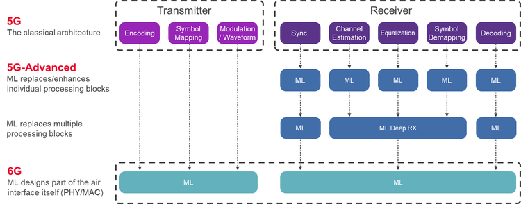
Figure 3. The three key phases toward a 6G AI-Native Air interface (Image source: The Integration of AI and 6G)
Some of these AI models may run on the UEs, some on the base stations, and some on both.
AI-assisted beamforming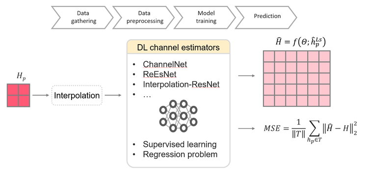
Figure 4. Channel estimation with supervised learning (Image source: How to Revolutionize 6G Research With AI-Driven Design)
AI is envisioned to:
- assist in ultra-massive multiple-input multiple-output (UM-MIMO) using more precise CSI
- predict optimal transmit beams
- reduce beam-pairing complexity
- assist reconfigurable intelligent surfaces (RIS) for environmental optimization
It’s hoped that AI will become instrumental in end-to-end network optimization and dynamically adapting the entire RAN through self-monitoring, self-organization, self-optimization, and self-healing.
Automated network managementAI holds the potential to automate network operation and maintenance as well as enable automated management services like predictive maintenance, intelligent data perception, on-demand capability addition, traffic prediction, and energy management.
Real-time dynamic allocation and scheduling of wireless resources like bandwidth and power for load balancing could be automatically handled by AI. AI-based mobility management could proactively manage handoffs and reduce signaling overhead.
Additionally, analysis of vast network data by AI promises precise threat intelligence, real-time monitoring, prediction, and active defense against network faults and security risks.
What AI techniques are most effective for validating 6G system-level performance?
Figure 5. 6G AI-based model validation (Image source: The Integration of AI and 6G)
AI is a wide field with many techniques, like deep learning, reinforcement learning, generative models, and machine learning. Let’s look at how these different AI algorithms and architectures could be used for 6G design, validation, and network performance testing.
Reinforcement learning (RL)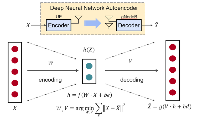
Figure 6. CSI feedback compression (Image source: How to Revolutionize 6G Research With AI-Driven Design)
RL has the potential to be at the forefront of AI for 6G self-optimization, network design, and testing because it is good at replicating human decision-making, testing on a massive scale, and enabling the recent rise of large reasoning models.
RL and deep RL could be used for the following use cases:
- RAN optimization: RL is already being used for intent-based RAN optimization in 5G, enabling autonomous decision-making in dynamic network environments, particularly for mobility management, interference mitigation, and energy-efficient scheduling. RL can control and optimize complex workflows.
- Enhanced beamforming: Deep RL could be used for beam prediction in the spatial and temporal domains.
- Functional testing: Autonomous agents, trained using RL, could test 6G hardware and software systems, looking for bugs as their rewards. Each agent will be a deep neural network trained using proximal policy optimization or direct preference optimization to do sequences of network actions and favor those sequences that are likely to maximize their rewards (the number of bugs found).
- Performance testing: In a 6G system, performance will be an emergent property of hundreds of interacting network parameters. Manually finding the combinations that lead to poor performance will be nearly impossible. An RL agent could automatically explore these combinations and identify configurations that result in performance bottlenecks.
DNNs could be used for the following:
- Channel estimation: DNNs and other deep learning architectures like Convolutional Neural Networks (CNNs) could estimate channel conditions, which will be crucial for overall system performance, especially in complex, high-noise environments.
- CSI compression: CNN-based autoencoders are poised to become the most commonly used architecture for CSI compression.
Transformer-based autoencoders (like Transnet) have been tested for compressing CSI feedback from UEs to a 5G base station and could be used for 6G too.
Graph neural networks (GNNs)GNNs are used to model the relational structure of network elements. They could learn spatial and topological patterns for tasks like mobility management, interference mitigation, and resource allocation.
They may also be used as physics-informed models for channel estimation reconstruction.
Generative adversarial networks (GANs)GANs will probably be used to learn and create realistic wireless channel data. They could also be used for denoising and anomaly detection.
Large reasoning and action modelsThese models are created from pre-trained large language models or large concept models by using RL to fine-tune them for reasoning and acting. They are the foundations of agentic AI. Agentic AI for 6G is still a very new research topic. Agentic AI’s ability for complex orchestration of smaller AI models, hardware, databases, and tools could make it suitable for testing 6G networks.
How is synthetic data generated by AI used in 6G testing and validation?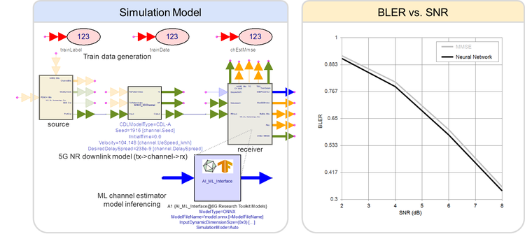
Figure 7. Using AI models in System Design (Image source: The Integration of AI and 6G)
A key benefit of AI will be its ability to synthesize test scenarios and data that simulates realistic 6G environments in lockstep with the 6G standards as they emerge and evolve in the coming years. Such synthesis could enhance designs and reduce development risks from day one.
The use of AI in network operations will lead to non-determinism and an explosion of possible outcomes that challenge testability and repeatability.
Design and test engineers will have to worry about how they can test all possible scenarios and edge cases. Physical deployments would not be possible until customer trials start. Even physical prototypes will be initially impossible and become expensive later on.
This is why AI-powered simulations and AI-generated realistic data are projected to become critical for 6G companies. AI could generate any type of large, realistic data needed to train and test the sophisticated AI/ML algorithms of 6G. The key technologies and techniques involved are outlined below:
- Digital twins: A digital twin is an accurate and detailed proxy for a real-world implementation, capable of emulating entire networks and individual components. These virtual representations will be key to simulating ultra-dense 6G environments. They could support integrated modeling of network environments and users to test complex RAN optimization problems.
- Generative AI models: GANs could become crucial for testing 6G wireless channels. A GAN could be trained on data from real-world 5G networks augmented with 6G-specific parameters calculated using known analytical models. The generator network would learn to synthesize realistic 6G data and simulate virtual channels for realistic environments, even accounting for geography. Later, measured data from 6G hardware prototypes could be included to enhance their realism.
- Specialized testbeds: Synthetic data is vital for studying new 6G sub-terahertz bands (100-300 GHz) because physical measurements are not practical. AI-generated scenarios based on data from sub-terahertz testbeds could recreate the complex impairments and nonlinearities expected at these frequencies.
- Simulation tools: Sophisticated visual tools like Keysight Channel Studio (RaySim) could simulate signal propagation and generate channel data in a specific environment, like a selected city area. It could model detailed characteristics like delay spread and user mobility, mimicking real-world conditions needed for training components like 6G neural receivers.
- Systems modeling platforms: An end-to-end system design platform like Keysight’s System Design will have the ability to generate high-quality 6G data for neural network training. It would combine system design budgets, 3GPP-compliant channel models (like clustered delay line models), measured data, and noise to produce diverse samples with varying noise and channel configurations.
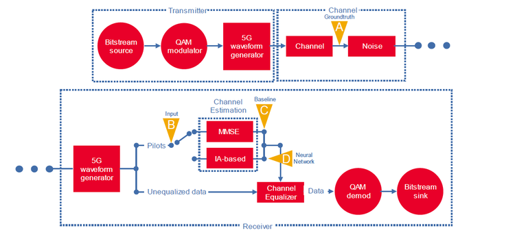
Figure 8. Wireless channel estimation (Image source: The Integration of AI and 6G)
AI techniques like anomaly detection and intelligent test automation could help you design and validate all the advanced chips and components that will go into 6G hardware for capabilities like sub-terahertz (THz)frequency bands and UM-MIMO.
Below, we speculate on how 6G and AI could be used for chip and hardware design.
Data-driven AI modelingThe behaviors of 6G technology enablers like UM-MIMO, reconfigurable intelligent surfaces, and sub-terahertz frequency bands will be too complex to fully characterize using analytical methods. Instead, neural networks could create accurate, data-driven, nonlinear AI models.
AI models in electronic design automation (EDA)EDA tools like Advanced Design System and Device Modeling could seamlessly integrate AI models for designing the high-frequency gallium nitride (GaN) radio frequency integrated circuits that’ll probably be needed in 6G. These tools could run artificial neural network models as part of circuit simulations and device modeling.
Validation of AI-enabled components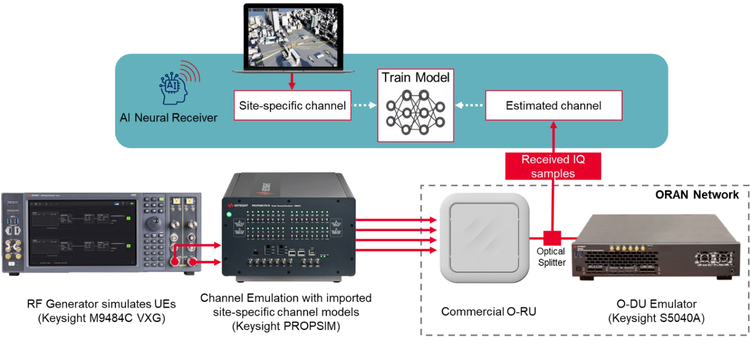
Figure 9. 6G AI neural receiver design and validation setup (Image source: The Integration of AI and 6G)
Validating the AI-native physical layer blocks (like neural receivers) will be paramount. Only AI-driven testing and automation could effectively tackle the black box nature and non-determinism of AI models.
AI-driven simulationsAI-driven simulation tools like Keysight RaySim could synthesize high-quality, site-specific channel data that — combined with deterministic, stochastic, and measured data — to create highly realistic environments for validating THz and MIMO designs.
Optimized beamforming and CSIAI models could potentially enhance beamforming by improving spectral efficiency. A problem with many antennas is the huge CSI feedback overhead. AI models like autoencoders could compress CSI feedback by as much as 25% without degrading efficiency and reliability.
Hardware-in-the-loop validationAI channel estimation models have the potential to handle multidimensionality and noise levels more robustly than traditional methods. They could be used by system design software and tested in hardware-in-the-loop setups (with channel emulators, signal generators, and digitizers) to assess effectiveness based on metrics like block error rate and signal-to-noise ratio.
Anomaly detectionAnomaly detection could be applied to data generated by AI simulations and models to identify unusual behaviors or deviations that may point to design flaws or operational issues.
What are the challenges and limitations of using AI in 6G design validation?Could AI and its results be trusted? Without careful design, every AI model is prone to out-of-distribution errors, data scarcity, poor model interpretability, overfitting, and hallucinations. A better question that your 6G and AI engineers must keep asking is, “How can we make our AI models, as well as AI-generated tests and data, more accurate and more trustworthy?”
For that, follow the recommendations below.
- Design for seamless integration: AI-based solutions must seamlessly integrate and agree with existing wireless principles built upon decades of tried-and-tested signal processing and communication theories. For example, a fully AI-designed physical layer that can dynamically change the waveform based on ambient conditions poses challenges for traditional measurement and design techniques like digital predistortion and amplifier design.
- Address data scarcity upfront: Real-world wireless data is often sparse. 6G ecosystems will probably be particularly challenging to characterize. Address this by augmenting data from 5G-Advanced networks with data calculated by 6G-specific analytical models. However, plan for extensive manual pre-processing because preparing realistic channel data to train models will not be trivial.
- Aim for model interpretability: To balance the opacity of powerful black-box techniques like deep neural networks, combine them with models that are more interpretable — like decision trees and random forests — through approaches like mixture-of-experts, ensembling, and explainable AI.
- Use physics-informed models: By bounding AI results with data from physics-informed models, engineers will be able to ensure that AI models operate within physical reality, making them robust and trustworthy. For example, reinforcement learning, which could be used for intent-based RAN optimization, can produce different results for the same input, generate out-of-bounds parameters, or fail to constrain to physical reality.
- Prevent overfitting: Sparse data and poor data diversity can lead to overfitting. For example, data generated under severe fading channel conditions is known to result in overfitting. Follow data augmentation and cross-validation best practices to counteract overfitting.
- Plan hardware-in-the-loop testing: Synthetically generated channels can be loaded into channel emulators like PROPSIM to test AI/ML algorithms in base stations and UEs. This will enable model advancements based on real failures and impairments.
- Avoid negative side effects: AI integration should not lead to excessive energy usage, unmanageable training data, or security risks. AI will greatly expand the threat surface, but since AI itself is quite new, cybersecurity risks are not well understood. This means 6G and AI integrations must be carefully designed for resilience and quick recovery from cyber attacks.
The post AI-Driven 6G: Smarter Design, Faster Validation appeared first on ELE Times.
Scaling up the Smart Manufacturing Mountain
Courtesy: Rockwell Automation
| A step-by-step roadmap to adopting smart manufacturing tools, boosting efficiency, and unifying systems for a smoother digital transformation journey. |
Embracing new technology in manufacturing is similar to ascending a mountain since it requires strategy, pacing, and the right gear. Rushing ahead without proper support can strain your systems as well as your people, but with thoughtful planning and timely technology selection, the climb becomes manageable and rewarding.
There are many paths to digital excellence. Integrating new technologies can significantly boost productivity and efficiency, but even the smoothest rollouts can come with hurdles. In our decades of experience working with customers, we’ve learned the importance of taking a measured approach to change to avoid unnecessary disruption. Here, we’ll lay out one way to approach digital transformation.
Beginning the Climb: Laying the Foundation
For many manufacturers, an accessible starting point for digital transformation is real-time production monitoring. Production monitoring enhances visibility and empowers your team to manage performance proactively—without overhauling existing workflows.
By consolidating machine and system data into a single dashboard, production monitoring eliminates silos and simplifies decision-making. It equips your team with actionable KPIs and insights from the shop floor to the executive suite.
With minimal investment in time, budget, and effort, real-time monitoring can deliver immediate value—which makes it an ideal first step on your digital journey.
Climbing Higher: Expanding Capabilities
While production monitoring is a strong foundation, it’s just the beginning. To unlock deeper efficiencies, manufacturers can next implement systems that offer broader control and insight across operations.
A modern manufacturing execution system (MES) is a prime example. By automating routine tasks, a MES reduces errors, cuts costs, and improves profitability. It also provides end-to-end visibility, communication, and traceability throughout the production lifecycle.
Pairing MES with a robust enterprise resource planning (ERP) system further enhances operational oversight. ERP tools help streamline compliance, manage risk, and align financial, operational, and IT strategies under one umbrella.
The real power lies in integrating these systems. When MES, ERP, and other tools work together in harmony, manufacturers can experience transformative results.
Reaching the Peak: Unlocking Full Potential
Even with a unified platform, there’s still room to elevate your operations. Today’s smart tools don’t just optimize—they redefine what’s possible.
Plex MES Automation and Orchestration leverages cutting-edge technology to connect machines and deliver unprecedented transparency and control. With intuitive low-code integration, your team can customize workflows and achieve seamless automation across the plant floor.
Gear Up for Your Digital Climb
According to our 10th Annual State of Smart Manufacturing report, many manufacturers feel they’re falling behind technologically compared to last year. If you’re exploring new solutions but unsure about the path forward, you’re not alone.
Whether you’re just beginning your smart manufacturing journey or seeking advanced, integrated solutions, we’d like to help! Check out our case study library to see how we’ve helped companies just like yours take on projects to advance their digital transformation journey.
The post Scaling up the Smart Manufacturing Mountain appeared first on ELE Times.
Singapore’s largest industrial district cooling system, Now operational at ST’s AMK TechnoPark
The District Cooling System at ST’s Ang Mo Kio (AMK) TechnoPark is operational and on time. Ms. Low Yen Ling, Senior Minister of State, Ministry of Trade and Industry & Ministry of Culture, Community and Youth, who joined ST in announcing this project in 2022, now took part in the inauguration ceremony. This launch is a critical milestone in ST’s goal to achieve carbon neutrality by 2027, and to work with local partners while also serving the communities as we move toward this sustainability objective.
Why a District Cooling System? Composition of a District Cooling System ST’s Ang Mo Kio TechnoPark in Singapore
In a DCS, one plant cools water before sending it to a network of underground pipes that serve various buildings. The system thus pools resources to increase efficiency, reduce environmental impacts, and save space. Buildings no longer need chillers, saving power and maintenance costs thanks to the central plant. Moreover, a loop sends the water back to the plant to cool it again. The main plant also stores water. Cooling therefore can happen during off-peak periods to improve the efficiency.
According to the Encyclopedia of Energy, the first significant DCS project dates back to 1962 and was installed in the United States. The technology garnered some interest in the 70s before subsiding. DCS became popular again in the 90s as regulators mandated chlorofluorocarbons (CFC) reduction. And now, district cooling systems gain new grounds as the world looks to reduce carbon emissions and recycle water.
Why the ST Ang Mo Kio TechnoPark?
Anatomy of a Unique Project
The AMK TechnoPark is ST’s largest wafer-production fab by volume. Bringing DCS to that particular site will thus have significant ripple effects. Traditionally, projects of this size target urban developments. For instance, the Deep Lake Water Cooling infrastructure in Toronto, Canada, has a similar capacity (40,000 tons), but the distribution network covers a chunk of the downtown area. The ST and SP Group infrastructure is thus unique because it’s one of the first at such a scale to cool an industrial manufacturing plant. It is also a first in the semiconductor industry. Most projects from competing fabs retrofit new chillers. With this new DCS, ST can re-purpose the space in favor of something much more efficient.
The project will cost an estimated USD 370 million, including the construction of the central cooling plant right next to the TechnoPark. Beyond energy savings, removing chillers within the ST plant will free up space for other environmental programs. For instance, the AMK site is looking at water conservation and solar panels, among other things. The SP Group should start construction of the central plant this year and is committed to managing the project for at least the next 20 years. Singapore also hopes that this project will inspire other companies. As Ms Low Yen Ling, Minister of State, Ministry of Culture, Community and Youth & Ministry of Trade and Industry stated, “I hope this initiative will inspire many more innovative decarbonization solutions across other industrial developments, and spur more companies to seek opportunities in sustainability.”
The post Singapore’s largest industrial district cooling system, Now operational at ST’s AMK TechnoPark appeared first on ELE Times.
Navitas consolidates Asian franchised distributor base
A makeshift motion-activated lamp
 | I had an awful lot of power outages lately and decided to make a lamp based on a 12V 10W LED I had laying around. It is controlled by a dimmer with a 555 timer, modified by connecting the reset pin to a switch. This gives the devices 3 modes - off, on, or triggered by a motion sensor. I am quite proud of myself for figuring out the motion activation without using an MCU. The device is powered by any qc/pd device via a trigger or an external battery. And yes, it would be better with a 3d printed case, but I had to move and couldn't take my 3d printers with me yet, so this one is held together with hot glue and hope for a better future cardboard. [link] [comments] |
Does (wearing) an Oura (smart ring) a day keep the doctor away?

Before diving into my on-finger impressions of Oura’s Gen3 smart ring, as I’d promised I’d do back in early September, I thought I’d start off by revisiting some of the business-related topics I mentioned in that initial post in the series. First off, I mentioned at the end of that post that Oura had just obtained a favorable final judgment from the United States International Trade Commission (ITC) that both China-based RingConn and India-based Ultrahuman had infringed on its patent portfolio. In the absence of licensing agreements or other compromises, both Oura competitors would be banned from further product shipments to and sales of their products in the US after a final 60-day review period ended on October 21, although retailer partners could continue to sell their existing inventory until it was depleted.
Product evolutions and competition developmentsI’m writing these words 10 days later, on Halloween, and there’ve been some interesting developments. I’d intentionally waited until after October 21 in order to see how both RingConn and Ultrahuman would react, as well as to assess whether patent challenges would pan out. As for Ultrahuman, a blog post posted shortly before the deadline (and updated the day after) made it clear that the company wasn’t planning on caving:
- A new ring design is already in development and will launch in the U.S. as soon as possible.
- We’re actively seeking clarity on U.S. manufacturing from our Texas facility, which could enable a “Made in USA” Ring AIR in the near future.
- We also eagerly await the U.S. Patent and Trademark Office’s review of the validity of Oura’s ‘178 patent, which it acquired in 2023, and is central to the ITC ruling. A decision is expected in December.
To wit, per a screenshot I captured the day after the deadline, Wednesday, October 22, sales through the manufacturer’s website to US customers had ceased.

And surprisingly, inventory wasn’t listed as available for sale on Amazon’s website, either.
RingConn conversely took a different tack. On October 22, again, when I checked, the company was still selling its products to US customers both from its own website and Amazon’s:


This situation baffled me until I hit up the company subreddit and saw the following:
Dear RingConn Family,
We’d like to share some positive news with you: RingConn, a leading smart ring innovator, has reached a settlement with ŌURA regarding a patent dispute. Under the terms of the agreement, RingConn’s software and hardware products will remain available in the U.S. market, without affecting its market presence.
See the company’s Reddit post for the rest of the message. And here’s the official press release.
Secondly, as I’d noted in my initial coverage:
One final factor to consider, which I continue to find both surprising and baffling, is the fact that none of the three manufacturers I’ve mentioned here seems to support having more than one ring actively associated with an account, therefore, cloud-logging and archiving data, at the same time. To press a second ring into service, you need to manually delete the first one from your account first. The lack of multi-ring support is a frequent cause of complaints on Reddit on elsewhere, from folks who want to accessorize multiple smart rings just as they do with normal rings, varying color and style to match outfits and occasions. And the fiscal benefit to the manufacturers of such support is intuitively obvious, yes?
It turns out I just needed to wait a few weeks. On October 1, Oura announced that multiple Oura Ring 4 styles would soon be supported under a single account. Quoting the press release, “Pairing and switching among multiple Oura Ring 4 devices on a single account will be available on iOS starting Oct. 1, 2025, and on Android starting Oct. 20, 2025.” That said, a crescendo of complaints on Reddit and elsewhere suggests an implementation delay; I’m 11 days past October 20 at this point and haven’t seen the promised Android app update yet, and at least some iOS users have waited a month at this point. Oura PR told me that I should be up and running by November 5; I’ll follow up in the comments as to whether this actually happened.
Charging optionsThat same day, by the way, Oura also announced its own branded battery-inclusive charger case, an omission that I’d earlier noted versus competitor RingConn:

That said, again quoting from the October 1 press release (with bolded emphasis mine), the “Oura Ring 4 Charging Case is $99 USD and will be available to order in the coming months.” For what it’s worth, the $28.99 (as I write these words) Doohoeek charging case for my Gen3 Horizon:

is working like a charm:


Behind it, by the way, is the upgraded Doohoeek $33.29 charging case for my Oura Ring 4, whose development story (which I got straight from the manufacturer) was not only fascinating in its own right but also gave me insider insight into how Oura has evolved its smart ring charging scheme for the smart ring over time. More about that soon, likely next month.

And here’s my Gen3 on the factory-supplied, USB-C-fed standard charger, again with its Ring 4 sibling behind it:

As for the ring itself, here’s what it looks like on my left index finger, with my wedding band two digits over from it on the same hand:


And here again are all three rings I’ve covered in in-depth writeups to date: the Oura Gen3 Horizon at left, Ultrahuman Ring AIR in the middle and RingConn Gen 2 at right:

Like RingConn’s product:

both the Heritage:

and my Horizon variant of the Oura Gen3:


include physical prompting to achieve and maintain proper placement: sensor-inclusive “bump” guides on both sides of the backside inside, which the Oura Ring 4 notably dispenses with:

I’ve already shown you what the red glow of the Gen3 intermediary SpO2 (oxygen saturation) sensor looks like when in operation, specifically when I’m able to snap a photo of it soon enough after waking to catch it still in action before it discerns that I’ve stirred and turns off:

And here’s what the two green-color pulse rate sensors, one on either side of their SpO2 sibling:

look like in action:

Generally speaking, the Oura Gen3 feels a lot like the Ultrahuman Ring AIR; they both drop between 15-20% of battery charge level every 24 hours, leading to a sub-week operating life between recharges. That said, I will give Oura well-deserved kudos for its software user interface, which is notably more informative, intuitive and more broadly easier to use than its RingConn and Ultrahuman counterparts. Then again, Oura’s been around the longest and has the largest user base, so it’s had more time (and more feedback) to fine-tune things. And cynically speaking, given Oura’s $5.99/month or $69.99/year subscription fee, versus competitors’ free, it’d better be better!
Software insightsIn closing, and in fairness, regarding that subscription, it’s not strictly required to use an Oura smart ring. That said, the information supplied without it:


is a pale subset of the norm:


What I’m showing in the overview screen images is a fraction of the total information captured and reported, but it’s all well-organized and intuitive. And as you can see on that last one, the Oura smart ring is adept at sensing even brief catnaps 
With that, and as I’ve already alluded, I now have an Oura Ring 4 on-finger—two of them, in fact, one of which I’ll eventually be tearing down—which I aspire to write up shortly, sharing my impressions both versus its Gen3 predecessor and its competitors. Until then, I as-always welcome your thoughts in the comments!
—Brian Dipert is the Principal at Sierra Media and a former technical editor at EDN Magazine, where he still regularly contributes as a freelancer.
Related Content
- The Smart Ring: Passing fad, or the next big health-monitoring thing?
- RingConn: Smart, svelte, and econ(omical)
- Can a smart ring make me an Ultrahuman being?
- Smarty Ring Fails to Impress
- Smart ring allows wearer to “air-write” messages with a fingertip
The post Does (wearing) an Oura (smart ring) a day keep the doctor away? appeared first on EDN.
Nimy gains CSIRO Kick-Start program funding for gallium exploration
STMicroelectronics’ new GaN ICs platform for motion control boosts appliance energy ratings
STMicroelectronics unveiled new smart power components that let home appliances and industrial drives leverage the latest GaN (gallium-nitride) technology to boost energy efficiency, increase performance, and save cost.
GaN power adapters and chargers available in the market can handle enough power for laptops and USB-C fast charging to achieve extremely high efficiency to meet stringent incoming eco-design norms. ST’s latest GaN ICs now make this technology applicable to motor drives for products like washing machines, hairdryers, power tools, and factory automation.
“Our new GaNSPIN system-in-package platform unleashes wide-bandgap efficiency gains in motion-control applications by introducing special features that optimize system performance and safeguard reliability,” said Domenico Arrigo, General Manager, Application Specific Products Division, STMicroelectronics. “The new devices enable future generations of appliances to achieve higher rotational speed for improved performance, with smaller and lower-cost control modules, lightweight form factors, and improved energy ratings.”
The first members of ST’s new family, the GANSPIN611 and GANSPIN612, can power motors of up to 400 Watts including domestic and industrial compressors, pumps, fans, and servo drives. Pin compatibility between the two devices ensures designs are easily scalable. GANSPIN611 is in production now, in a 9mm x 9mm thermally enhanced QFN package, from $4.44.
Technical notes on GaNSPIN drivers:
In the new GaNSPIN system-in-package, unlike in general-purpose GaN drivers, the driver controls turn-on and turn-off times in hard switching to relieve stress on the motor windings and minimize electromagnetic noise. The nominal slew rate (dV/dt) of 10V/ns preserves reliability and eases compliance with electromagnetic compatibility (EMC) regulations such as the EU EMC directive. Designers can adjust the turn-on dV/dt of both GaN drivers to fine-tune the switching performance according to the motor characteristics.
The post STMicroelectronics’ new GaN ICs platform for motion control boosts appliance energy ratings appeared first on ELE Times.
Inside the battery: A quick look at internal resistance

Ever wondered why a battery that reads full voltage still struggles to power your device? The answer often lies in its internal resistance. This hidden factor affects how efficiently a battery delivers current, especially under load.
In this post, we will briefly examine the basics of internal resistance—and why it’s a critical factor in real-world performance, from handheld flashlights to high-power EV drivetrains.
What’s internal resistance and why it matters
Every battery has some resistance to the flow of current within itself—this is called internal resistance. It’s not a design flaw, but a natural consequence of the materials and construction. The electrolyte, electrodes, and even the connectors all contribute to it.
Internal resistance causes voltage to drop when the battery delivers current. The higher the current draw, the more noticeable the drop. That is why a battery might read 1.5 V at rest but dip below 1.2 V under load—and why devices sometimes shut off even when the battery seems “full.”
Here is what affects it:
- Battery type: Alkaline, lithium-ion, and NiMH cells all have different internal resistances.
- Age and usage: Resistance increases as the battery wears out.
- Temperature: Cold conditions raise resistance, reducing performance.
- State of charge: A nearly empty battery often shows higher resistance.
Building on that, internal resistance gradually increases as batteries age. This rise is driven by chemical wear, electrode degradation, and the buildup of reaction byproducts. As resistance climbs, the battery becomes less efficient, delivers less current, and shows more voltage drop under load—even when the resting voltage still looks healthy.
Digging a little deeper—focusing on functional behavior under load—internal resistance is not just a single value; it’s often split into two components. Ohmic resistance comes from the physical parts of the battery, like the electrodes and electrolyte, and tends to stay relatively stable.
Polarization resistance, on the other hand, reflects how the battery’s chemical reactions respond to current flow. It’s more dynamic, shifting with temperature, charge level, and discharge rate. Together, these resistances shape how a battery performs under load, which is why two batteries with identical voltage readings might behave very differently in real-world use.
Internal resistance in practice
Internal resistance is a key factor in determining how much current a battery can deliver. When internal resistance is low, the battery can supply a large current. But if the resistance is high, the current it can provide drops significantly. Also, higher the internal resistance, the greater the energy loss—this loss manifests as heat. That heat not only wastes energy but also accelerates the battery’s degradation over time.
The figure below illustrates a simplified electrical model of a battery. Ideally, internal resistance would be zero, enabling maximum current flow without energy loss. In practice, however, internal resistance is always present and affects performance.

Figure 1 Illustration of a battery’s internal configuration highlights the presence of internal resistance. Source: Author
Here is a quick side note regarding resistance breakdown. Focusing on material-level transport mechanisms, battery internal resistance comprises two primary contributors: electronic resistance, driven by electron flow through conductive paths, and ionic resistance, governed by ion transport within the electrolyte.
The total effective resistance reflects their combined influence, along with interfacial and contact resistances. Understanding this layered structure is key to diagnosing performance losses and carrying out design improvements.
As observed nowadays, elevated internal resistance in EV batteries hampers performance by increasing heat generation during acceleration and fast charging, ultimately reducing driving range and accelerating cell degradation.
Fortunately, several techniques are available for measuring a battery’s internal resistance, each suited to different use cases and levels of diagnostic depth. Common methods include direct current internal resistance (DCIR), alternating current internal resistance (ACIR), and electrochemical impedance spectroscopy (EIS).
And there is a two-tier variation of the standard DCIR technique, which applies two sequential discharge loads with distinct current levels and durations. The battery is first discharged at a low current for several seconds, followed by a higher current for a shorter interval. Resistance values are calculated using Ohm’s law, based on the voltage drops observed during each load phase.
Analyzing the voltage response under these conditions can reveal more nuanced resistive behavior, particularly under dynamic loads. However, the results remain strictly ohmic and do not provide direct information about the battery’s state of charge (SoC) or capacity.
Many branded battery testers, such as some product series from Hioki, apply a constant AC current at a measurement frequency of 1 kHz and determine the battery’s internal resistance by measuring the resulting voltage with an AC voltmeter (AC four-terminal method).

Figure 2 The Hioki BT3554-50 employs AC-IR method to achieve high-precision internal resistance measurement. Source: Hioki
The 1,000-hertz (1 kHz) ohm test is a widely used method for measuring internal resistance. In this approach, a small 1-kHz AC signal is applied to the battery, and resistance is calculated using Ohm’s law based on the resulting voltage-to-current ratio.
It’s important to note that AC and DC methods often yield different resistance values due to the battery’s reactive components. Both readings are valid—AC impedance primarily reflects the instantaneous ohmic resistance, while DC measurements capture additional effects such as charge transfer and diffusion.
Notably, the DC load method remains one of the most enduring—and nostalgically favored—approaches for measuring a battery’s internal resistance. Despite the rise of impedance spectroscopy and other advanced techniques, its simplicity and hands-on familiarity continue to resonate with seasoned engineers.
It involves briefly applying a load—typically for a second or longer—while measuring the voltage drop between the open-circuit voltage and the loaded voltage. The internal resistance is then calculated using Ohm’s law by dividing the voltage drop by the applied current.
A quick calculation: To estimate a battery’s internal resistance, you can use a simple voltage-drop method when the open-circuit voltage, loaded voltage, and current draw are known. For example, if a battery reads 9.6 V with no load and drops to 9.4 V under a 100-mA load:
Internal resistance = 9.6 V-9.4 V/0.1 A = 2 Ω
This method is especially useful in field diagnostics, where direct resistance measurements may not be practical, but voltage readings are easily obtained.
In simplified terms, internal resistance can be estimated using several proven techniques. However, the results are influenced by the test method, measurement parameters, and environmental conditions. Therefore, internal resistance should be viewed as a general diagnostic indicator—not a precise predictor of voltage drop in any specific application.
Bonus blueprint: A closing hardware pointer
For internal resistance testing, consider the adaptable e-load concept shown below. It forms a simple, reliable current sink for controlled battery discharge, offering a practical starting point for further refinement. As you know, the DC load test method allows an electronic load to estimate a battery’s internal resistance by observing the voltage drop during a controlled current draw.

Figure 3 The blueprint presents an electronic load concept tailored for internal resistance measurement, pairing a low-RDS(on) MOSFET with a precision load resistor to form a controlled current sink. Source: Author
Now it’s your turn to build, tweak, and test. If you have got refinements, field results, or alternate load strategies, share them in the comments. Let us keep the circuit conversation flowing.
 T. K. Hareendran is a self-taught electronics enthusiast with a strong passion for innovative circuit design and hands-on technology. He develops both experimental and practical electronic projects, documenting and sharing his work to support fellow tinkerers and learners. Beyond the workbench, he dedicates time to technical writing and hardware evaluations to contribute meaningfully to the maker community.
Related Content
- All About Batteries
- What Causes Batteries to Fail?
- Power Consumption and Battery Life Analysis
- Resistivity is the key to measuring electrical resistance
- Cell balancing maximizes the capacity of multi-cell batteries
The post Inside the battery: A quick look at internal resistance appeared first on EDN.
PCB Easter eggs on Zebra printers
 | submitted by /u/freeflight_ua [link] [comments] |
Workbench and work area.
 | I can never keep this clean, its one thing after another. [link] [comments] |
Quantum Critical Metals and Nusano collaborate on developing and refining critical minerals in North America
Quantum Critical Metals and Nusano collaborate on developing and refining critical minerals in North America
Thank God they included the High Power Imported Heater with my new soldering iron.
 | It would've been a shame if it was domestic [link] [comments] |


